fegeometry
Description
An fegeometry object contains a geometry for use
in a finite element analysis with an femodel
object.
Creation
Syntax
Description
gm = fegeometry(geometry,Name=Value)fegeometry object using one or more name-value arguments.
For this syntax, geometry must specify a path to an STL or STEP
file.
gm = fegeometry(mesh)fegeometry object from a mesh represented by an
FEMesh object. If the mesh data identifies multiple faces for a 2-D
geometry or multiple cells for a 3-D geometry, the resulting geometry contains
corresponding multiple faces or cells.
gm = fegeometry(___,ElementIDToRegionID)FEMesh
object or by nodes and elements.
ElementIDToRegionID specifies the domain IDs for each element of
the mesh.
Input Arguments
Name-Value Arguments
Properties
Object Functions
addCell | Combine two geometries by adding one inside a cell of another |
addFace | Fill void regions in 2-D and split cells in 3-D geometry |
addVertex | Add vertex on geometry boundary |
addVoid | Create void regions inside 3-D geometry |
cellEdges | Find edges belonging to boundaries of specified cells |
cellFaces | Find faces belonging to specified cells |
discreteGeometry | Discrete 2-D or 3-D geometry description |
extrude | Vertically extrude 2-D geometry or specified faces of 3-D geometry |
faceEdges | Find edges belonging to specified faces |
facesAttachedToEdges | Find faces attached to specified edges |
generateMesh | Create triangular or tetrahedral mesh |
mergeCells | Merge geometry cells |
nearestEdge | Find edges nearest to specified point |
nearestFace | Find faces nearest to specified point |
pdegplot | Plot PDE geometry |
pdemesh | Plot PDE mesh |
rotate | Rotate geometry |
scale | Scale geometry |
translate | Translate geometry |
triangulation | Create triangulation object from
fegeometry |
Examples
Create an fegeometry object from a DiscreteGeometry object by assigning it to an femodel object for a finite element analysis.
Create and plot a 3-D geometry consisting of three nested cuboids of the same height.
gm = multicuboid([2 3 5],[4 6 10],3);
pdegplot(gm,CellLabels="on",FaceAlpha=0.3)
Create an femodel object for solving a static structural problem and assign the geometry to the model.
model = femodel(AnalysisType="structuralStatic", ...
                Geometry=gm);
model.Geometry
ans =
  fegeometry with properties:

       NumCells: 3
       NumFaces: 18
       NumEdges: 36
    NumVertices: 24
       Vertices: [24×3 double]
           Mesh: []
Create an fegeometry object from an STL file representing a forearm link, and use it for a finite element analysis with an femodel object.
Create an femodel object for solving a static structural problem, and assign the geometry to the model.
model = femodel(AnalysisType="structuralStatic", ...
                Geometry="ForearmLink.stl");
model.Geometry
ans =
  fegeometry with properties:

       NumCells: 1
       NumFaces: 147
       NumEdges: 329
    NumVertices: 213
       Vertices: [213×3 double]
           Mesh: []
Plot the geometry.
pdegplot(model,FaceAlpha=0.3)

Create an fegeometry object from a function handle.
gm = fegeometry(@cardg)
gm =
  fegeometry with properties:

       NumCells: 0
       NumFaces: 1
       NumEdges: 4
    NumVertices: 4
       Vertices: [4×2 double]
           Mesh: []
Plot the geometry with the edge labels.
pdegplot(gm,EdgeLabels="on");
Create an fegeometry object from a geometry description matrix.
g = [3 4 0 1 1 0 0 0 1.0 1.0];
sf = 'S1';
ns = 'S1';
gm = fegeometry(decsg(g',sf,ns'))
gm =
  fegeometry with properties:

       NumCells: 0
       NumFaces: 1
       NumEdges: 4
    NumVertices: 4
       Vertices: [4×2 double]
           Mesh: []
Plot the geometry with the edge labels.
pdegplot(gm,EdgeLabels="on");
xlim([-0.1 1.1])
ylim([-0.1 1.1])
Since R2023b
Create an fegeometry object from a 2-D triangulation object.
Define the points in a 2-D triangulation.
P = [2.5 8.0;
     6.5 8.0;
     2.5 5.0;
     6.5 5.0;
     1.0 6.5;
     8.0 6.5];
Define the triangulation connectivity list.
T = [5 3 1;
     3 2 1;
     3 4 2;
     4 6 2];
Create the triangulation representation.
TR = triangulation(T,P)
TR =
  triangulation with properties:

              Points: [6×2 double]
    ConnectivityList: [4×3 double]
Create an fegeometry object from the triangulation object TR.
gm = fegeometry(TR)
gm =
  fegeometry with properties:

       NumCells: 0
       NumFaces: 1
       NumEdges: 6
    NumVertices: 6
       Vertices: [6×3 double]
           Mesh: [1×1 FEMesh]
The created geometry includes a linear mesh.
gm.Mesh
ans =
  FEMesh with properties:

             Nodes: [2×6 double]
          Elements: [3×4 double]
    MaxElementSize: 5
    MinElementSize: 2.1213
     MeshGradation: []
    GeometricOrder: 'linear'
To create a more accurate quadratic mesh, use generateMesh.
gm = generateMesh(gm);
gm.Mesh
ans =
  FEMesh with properties:

             Nodes: [2×871 double]
          Elements: [6×408 double]
    MaxElementSize: 0.3046
    MinElementSize: 0.1523
     MeshGradation: 1.5000
    GeometricOrder: 'quadratic'
Since R2024b
Create a spherical geometry from a mesh represented by an FEMesh object and from a mesh represented by nodes and elements.
First, create and plot a mesh.
model = createpde;
model.Geometry = multisphere(10);
msh = generateMesh(model);
pdemesh(msh)
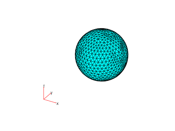
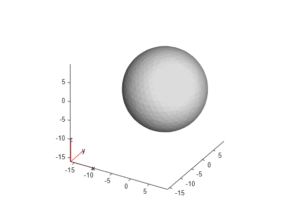
Create an fegeometry object representing a sphere by using the FEMesh object msh.
g1 = fegeometry(msh)
g1 =
  fegeometry with properties:

       NumCells: 1
       NumFaces: 1
       NumEdges: 0
    NumVertices: 0
       Vertices: []
           Mesh: [1×1 FEMesh]
Plot the resulting geometry.
pdegplot(g1)

Create an fegeometry object representing the same sphere by using the mesh nodes and elements as input arguments. Transpose the arrays representing the nodes and elements.
g2 = fegeometry(msh.Nodes',msh.Elements')
g2 =
  fegeometry with properties:

       NumCells: 1
       NumFaces: 1
       NumEdges: 0
    NumVertices: 0
       Vertices: []
           Mesh: [1×1 FEMesh]
Plot the resulting geometry.
pdegplot(g2)
Create a 2-D multidomain geometry from a planar mesh.
The MultidomainMesh2D file, which is included in Partial Differential Equation Toolbox™, contains a 2-D mesh. Load information about nodes, elements, and element-to-domain correspondence into your workspace.
load MultidomainMesh2DCreate a geometry from the mesh nodes and elements.
gm = fegeometry(nodes',elements',ElementIdToRegionId);
Plot the geometry with the face labels.
pdegplot(gm,FaceLabels="on")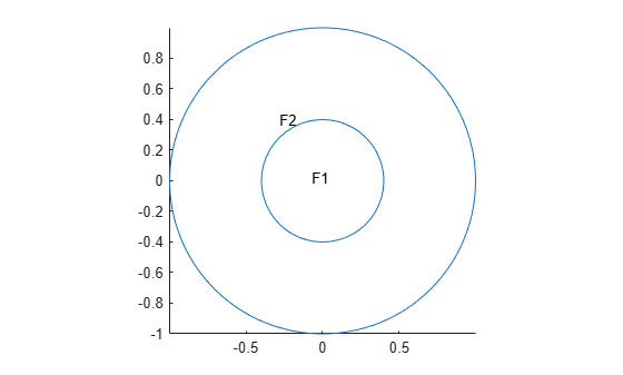
Since R2024b
Create two geometries from a mesh, one with two cells and another with one cell.
The TwoCellMesh file contains a 3-D mesh specified by an FEMesh object and a vector specifying element-to-domain correspondence. Each vector element is a cell ID for an element of the mesh. Load this data into your workspace.
load TwoCellMesh;Create a geometry from the mesh.
gm2cells = fegeometry(msh);
Plot the geometry with the cell labels.
pdegplot(gm2cells,CellLabels="on",FaceAlpha=0.3)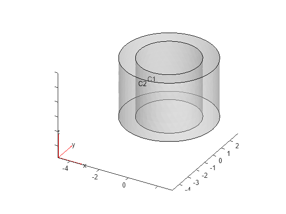
Now, modify vector ElementIDToRegionID, which specifies the element-to-domain correspondence, so that all elements of the mesh belong to cell 1.
ElementIDToRegionID(:) = 1;
Create a geometry from the mesh. The resulting geometry has one cell.
gm1cell = fegeometry(msh,ElementIDToRegionID);
Plot the geometry with the cell label.
pdegplot(gm1cell,CellLabels="on",FaceAlpha=0.3)
Since R2024a
Check for self-intersections while importing the geometry of a cover.
Create an fegeometry object from an STL file and plot the
geometry.
gm = fegeometry("Cover.stl");
pdegplot(gm)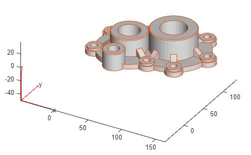
Create an femodel object for solving a static structural problem,
and assign the geometry to the model.
model = femodel(AnalysisType="structuralStatic", ...
                Geometry=gm);
Generate a mesh and assign the result to the model to update the mesh stored in the
Geometry property of the model. The mesh generator issues a warning
about poor quality of some of the mesh elements.
model = generateMesh(model);
Warning: Found elements with poor shape quality.
(Type "warning off pde:pdeMeshGenerator:ElementQualityWarn" to suppress this warning.)
> In pde.EquationModel/generateMesh (line 104)
In fegeometry/generateMesh (line 220)
In femodel/generateMesh (line 344)
Rotate the geometry plot to check for any problematic areas. By looking at the top of the geometry, you can see that three of the cylinders might be in contact with each other or intersecting each other.
figure
pdegplot(gm)
view([30 90])

Use the AllowSelfIntersections argument to check for
self-intersections while importing a geometry. If you set this argument to
false, fegeometry does not allow the import if a
geometry has self-intersections.
gm = fegeometry("Cover.stl",AllowSelfIntersections=false)Unable to import a self-intersecting geometry.
Tips
For 3-D geometries symmetrical around an axis of rotation, you can speed up computations by simplifying a 3-D geometry to a 2-D geometry and setting the
PlanarTypeproperty offemodelto"axisymmetric". The axis of rotation is the vertical axis, x = 0. The x–axis represents the radial component, and the y–axis represents the axial component.
Version History
Introduced in R2023aSee Also
Functions
generateMesh|pdegplot|addCell|addFace|addVertex|addVoid|rotate|scale|translate|extrude|cellEdges|cellFaces|faceEdges|facesAttachedToEdges|nearestEdge|nearestFace