DUT Subsystem Guidelines
You can follow these guidelines to learn some best practices on how you can model the DUT for HDL code and testbench generation. Each guideline has a severity level that indicates the level of compliance requirements. To learn more, see HDL Modeling Guidelines Severity Levels.
DUT Subsystem Considerations
Guideline ID
1.2.1
Severity
Strongly Recommended
Description
The DUT is the Subsystem that contains the algorithm for which you want to generate code. Generally, you specify the top-level Subsystem as the DUT. See also Partition Model into DUT and Test Bench.
Consider using these recommended settings when you design the DUT Subsystem for HDL code generation.
Make sure that the HDL Architecture of the DUT is not specified as a
BlackBox. See BlackBox Subsystems.Connect output signals that are unconnected to a Terminator block. To learn more, see Terminate Unconnected Block Outputs.
For a non-top DUT, specify the DUT as a nonvirtual Subsystem before generating HDL code to avoid numerical mismatches in the simulation results. To learn more, see Usage of Different Subsystem Types.
Convert DUT Subsystem to Model Reference for Testbenches with Continuous Blocks
Guideline ID
1.2.2
Severity
Strongly Recommended
Description
In some cases, parts of the Simulink™ testbench can contain Simscape™ blocks or other blocks from the Simulink library that operate at a continuous sample time. To simulate these blocks, you must specify a continuous solver setting for your model. The solver settings that you specify applies to all blocks in your model. This means that the DUT Subsystem uses a continuous solver, which is not supported for HDL code generation. To generate HDL code, convert the DUT Subsystem to a model reference, and then use a fixed-step discrete solver for the referenced model. As the parent model and the referenced model use different solver settings, you must convert the sample time by inserting Zero-Order Hold and Rate Transition blocks at the DUT boundary.
For example, open the model hdlcoder_testbench_continuous.slx. The model uses ode45, which is a continuous solver setting. You see that the DUT is a Model block. Zero-Order Hold and Rate Transition blocks at the boundary convert the sample time.
open_system('hdlcoder_testbench_continuous')
set_param('hdlcoder_testbench_continuous','SimulationCommand','Update')
get_param('hdlcoder_testbench_continuous', 'Solver')
ans =

    'ode45'
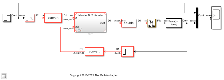
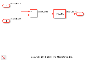
To see the referenced model hdlcoder_DUT_discrete, double-click the DUT block. You see that the DUT uses a discrete solver setting.
open_system('hdlcoder_testbench_continuous/DUT')
get_param('hdlcoder_DUT_discrete', 'Solver')
ans =

    'FixedStepDiscrete'
Insert Handwritten Code into Simulink Modeling Environment
Guideline ID
1.2.3
Severity
Informative
Description
You can reuse a pre-verified RTL IP or insert your handwritten HDL code into the Simulink® modeling environment by using these methods:
Verilog HDL Import
If you have handwritten Verilog code, you can import the code into the Simulink environment. The import process generates a Simulink model that is functionally equivalent to your handwritten HDL code.
HDL import supports a subset of Verilog constructs that you can use for importing your design to create the Simulink model. To learn more, see:
BlackBox Subsystems
You can use BlackBox subsystems to insert your handwritten HDL code for a block in your Simulink model. You can then integrate BlackBox subsystems with other blocks in your Simulink model and then generate HDL code.
To make the BlackBox Subsystem compatible with other blocks for HDL code generation and to include this block in your model, create the block in Simulink:
Name the block by using the same name as the VHDL entity, or Verilog or SystemVerilog module.
Define the same inputs and outputs, including the same types, sizes, and names.
Define the same clock, reset, and clock enable signals. A single block can have not more than one clock, reset, and clock enable signal.
Use a single sample rate for the block.
Specify the Architecture of the block as
BlackBoxin the HDL Block Properties.
To learn more, see Generate Black Box Interface for Subsystem.
DocBlock in BlackBox Subsystems
To keep the HDL code with your model, instead of as a separate file, use a DocBlock to integrate custom HDL code. You can use your own handwritten VHDL, Verilog or SystemVerilog code as the text in the DocBlock.
You include each DocBlock that contains custom HDL code by placing it in a black box subsystem, and including the black box subsystem in your DUT. One HDL file is generated per black box subsystem. For more information, see Integrate Custom HDL Code by Using DocBlock.
HDL Cosimulation Blocks
If you have a HDL simulator such as Siemens® ModelSim™ or Cadence Incisive®, you can use HDL Cosimulation (HDL Verifier) blocks to simulate the HDL code for the DUT by using that HDL simulator.
You can simulate the HDL code for the DUT in Simulink and instantiate the HDL code in the generated code for the DUT.