fusionRadarSensor
Generate detections or track reports
Description
The fusionRadarSensor System object™ generates detections or track reports of
targets. You can specify the detection mode of the sensor as monostatic, bistatic, or
electronic support measures (ESM) through the DetectionMode property. You
can use fusionRadarSensor to simulate clustered or unclustered detections with
added random noise, and also generate false alarm detections. You can fuse the generated
detections with other sensor data and track objects using a multi-object tracker, such as
trackerGNN. You can
also output tracks directly from the fusionRadarSensor object. To configure whether
targets are output as clustered detections, unclustered detections, or tracks, use the
TargetReportFormat property. You can add fusionRadarSensor
to a Platform and then
use the radar in a trackingScenario.
Using a single-exponential model, the radar computes range and elevation biases caused by propagation through the troposphere. A range bias means that measured ranges are greater than the line-of-sight range to the target. Elevation bias means that the measured elevations are above their true elevations. Biases are larger when the line-of-sight path between the radar and target passes through lower altitudes because the atmosphere is thicker at these altitudes. See References for more details.
To generate radar detections or track reports:
Create the
fusionRadarSensorobject and set its properties.Call the object with arguments, as if it were a function.
To learn more about how System objects work, see What Are System Objects?
Creation
Syntax
Description
rdr = fusionRadarSensor
rdr = fusionRadarSensor(id)id.
rdr = fusionRadarSensor(___,scanConfig)scanConfig. You can specify
scanConfig as 'No scanning',
'Raster', 'Rotator', or
'Sector'. See Convenience Syntaxes for more details on
these configurations.
rdr = fusionRadarSensor(___,Name,Value)radarDataGenerator('TargetReportFormat','Tracks','FilterInitializationFcn',@initcvkf)
creates a radar sensor that generates track reports using a tracker initialized by a
constant-velocity linear Kalman filter.
Properties
Usage
Syntax
Description
Monostatic Detection Mode
These syntaxes apply when you set the DetectionMode property to
'Monostatic'.
reports = rdr(targetPoses,simTime)reports from the target poses,
targetPoses, at the current simulation time,
simTime. The object can generate reports for multiple targets. To
enable this syntax:
Set the
DetectionModeproperty to'Monostatic'.Set the
InterferenceInputPortproperty tofalse.Set the
EmissionsInputPortproperty tofalse.
reports = rdr(targetPoses,interferences,simTime)interferences, in the radar
signal transmission. To enable this syntax:
Set the
DetectionModeproperty to'Monostatic'.Set the
InterferenceInputPortproperty totrue.Set the
EmissionsInputPortproperty tofalse.
reports = rdr(emissions,emitterConfigs,simTime)emissions, and the configurations of the corresponding emitters,
emitterConfigs, that generate the emissions. To enable this
syntax:
Set the
DetectionModeproperty to'Monostatic'.Set the
InterferenceInputPortproperty tofalse.Set the
EmissionsInputPortproperty totrue.
Bistatic or ESM Detection Mode
This syntax applies when you set the DetectionMode property to
'Bistatic' or 'ESM'. In these two modes, the
TargetReportFormat can only be 'Detections' and
the DetectionCoordinates can only be 'Sensor
spherical'.
Provide INS Input
This syntax applies when you set the HasINS property to
true.
[___] = rdr(___,
specifies the pose information of the radar platform through an INS estimate. Notice
that the insPose,simTime)insPose argument is the second to the last argument before
the simTime argument. This syntax can be used with any of the
previous syntaxes. See the HasINS
property for more details.
Output Additional Information
Use this syntax if you want to output additional information of the reports.
[
returns the number of reports, reports,numReports,config] = rdr(___)numReports, and the configuration of
the radar, config, at the current simulation time.
Input Arguments
Output Arguments
Object Functions
To use an object function, specify the
System object™ as the first input argument. For
example, to release system resources of a System object named obj, use
this syntax:
release(obj)
Examples
Create three targets by specifying their platform ID, position, and velocity.
tgt1 = struct('PlatformID',1, ...
    'Position',[0 -50e3 -1e3], ...
    'Velocity',[0 900*1e3/3600 0]);

tgt2 = struct('PlatformID',2, ...
    'Position',[20e3 0 -500], ...
    'Velocity',[700*1e3/3600 0 0]);

tgt3 = struct('PlatformID',3, ...
    'Position',[-20e3 0 -500], ...
    'Velocity',[300*1e3/3600 0 0]);
Create an airport surveillance radar that is 15 meters above the ground.
rpm = 12.5;
fov = [1.4; 5]; % [azimuth; elevation]
scanrate = rpm*360/60;  % deg/s
updaterate = scanrate/fov(1); % Hz

sensor = fusionRadarSensor(1,'Rotator', ...
    'UpdateRate',updaterate, ...
    'MountingLocation',[0 0 -15], ...
    'MaxAzimuthScanRate',scanrate, ...
    'FieldOfView',fov, ...
    'AzimuthResolution',fov(1));
Generate detections from a full scan of the radar.
simTime = 0;
detBuffer = {};
while true
    [dets,numDets,config] = sensor([tgt1 tgt2 tgt3],simTime);
    detBuffer = [detBuffer; dets]; %#ok<AGROW>

    % Is full scan complete?
    if config.IsScanDone
        break % yes
    end
    simTime = simTime + 1/sensor.UpdateRate;
end

radarPosition = [0 0 0];
tgtPositions = [tgt1.Position; tgt2.Position; tgt3.Position];
Visualize the results.
clrs = lines(3);

figure
hold on

% Plot radar position
plot3(radarPosition(1),radarPosition(2),radarPosition(3),'Marker','s', ...
    'DisplayName','Radar','MarkerFaceColor',clrs(1,:),'LineStyle','none')

% Plot truth
plot3(tgtPositions(:,1),tgtPositions(:,2),tgtPositions(:,3),'Marker','^', ...
    'DisplayName','Truth','MarkerFaceColor',clrs(2,:),'LineStyle', 'none')

% Plot detections
if ~isempty(detBuffer)
    detPos = cellfun(@(d)d.Measurement(1:3),detBuffer, ...
        'UniformOutput',false);
    detPos = cell2mat(detPos')';
    plot3(detPos(:,1),detPos(:,2),detPos(:,3),'Marker','o', ...
        'DisplayName','Detections','MarkerFaceColor',clrs(3,:),'LineStyle','none')
end

xlabel('X(m)')
ylabel('Y(m)')
axis('equal')
legend

Create an radar emission and then detect the emission using a fusionRadarSensor object.
First, create an radar emission.
orient = quaternion([180 0 0],'eulerd','zyx','frame');
rfSig = radarEmission('PlatformID',1,'EmitterIndex',1,'EIRP',100, ...
    'OriginPosition',[30 0 0],'Orientation',orient);
Then, create an ESM sensor using fusionRadarSensor.
sensor = fusionRadarSensor(1,'DetectionMode','ESM');
Detect the RF emission.
time = 0;
[dets,numDets,config] = sensor(rfSig,time)
dets = 1×1 cell array
    {1×1 objectDetection}
numDets =
1
config = struct with fields:
              SensorIndex: 1
              IsValidTime: 1
               IsScanDone: 0
              FieldOfView: [1 5]
              RangeLimits: [0 Inf]
          RangeRateLimits: [0 Inf]
    MeasurementParameters: [1×1 struct]
Algorithms
The fusionRadarSensor System object can model three detection modes:
monostatic, bistatic, and electronic support measures (ESM) as shown in the following
figures.
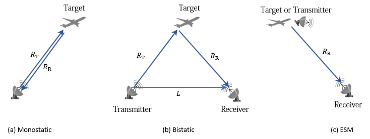
For the monostatic detection mode, the transmitter and the receiver are collocated, as shown in figure (a). In this mode, the range measurement R can be expressed as R = RT = RR, where RT and RR are the ranges from the transmitter to the target and from the target to the receiver, respectively. In the radar sensor, the range measurement is R = ct/2, where c is the speed of light and t is the total time of the signal transmission. Other than the range measurement, a monostatic sensor can also optionally report range-rate, azimuth, and elevation measurements of the target.
For the bistatic detection mode, the transmitter and the receiver are separated by a distance L. As shown in figure (b), the signal is emitted from the transmitter, reflected from the target, and received by the receiver. The bistatic range measurement Rb is defined as Rb = RT + RR − L. In the radar sensor, the bistatic range measurement is obtained by Rb = cΔt, where Δt is the time difference between the receiver receiving the direct signal from the transmitter and receiving the reflected signal from the target. Other than the bistatic range measurement, a bistatic sensor can also optionally report the bistatic range-rate, azimuth, and elevation measurements of the target. Since the bistatic range and the two bearing angles (azimuth and elevation) do not correspond to the same position vector, they cannot be combined into a position vector and reported in a Cartesian coordinate system. As a result, the measurements of a bistatic sensor can only be reported in a spherical coordinate system.
For the ESM detection mode, the receiver can only receive a signal reflected from the target or directly emitted from the transmitter, as shown in figure (c). Therefore, the only available measurements are azimuth and elevation of the target or transmitter. These measurements can only be reported in a spherical coordinate system.
The MeasurementParameters property of an output detection consists
of an array of structures that describes a sequence of coordinate transformations from a
child frame to a parent frame, or the inverse transformations. In most cases, the longest
required sequence of transformations is Sensor → Platform → Scenario.
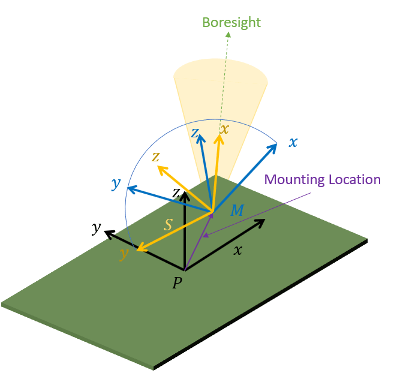
If the detections are reported in sensor spherical coordinates and
HasINS is set to false, then the sequence consists
only of one transformation from sensor to platform. In this transformation, the
OriginPosition is same as the MountingLocation
property of the sensor. The Orientation consists of two consecutive
rotations. The first rotation, corresponding to the MountingAngles
property of the sensor, accounts for the rotation from the platform frame
(P) to the sensor mounting frame (M). The second
rotation, corresponding to the azimuth and elevation angles of the sensor, accounts for the
rotation from the sensor mounting frame (M) to the sensor scanning frame
(S). In the S frame, the
x-direction is the boresight direction, and the
y-direction lies within the x-y
plane of the sensor mounting frame (M).
If HasINS is true, the sequence of
transformations consists of two transformations: first from the scenario frame to the
platform frame, and then from the platform frame to the sensor scanning frame. In the first
transformation, the Orientation is the rotation from the scenario frame
to the platform frame, and the OriginPosition is the position of the
platform frame origin relative to the scenario frame.
If the detections are reported in platform rectangular coordinates and
HasINS is set to false, the transformation
consists only of the identity.
The table shows the fields of the MeasurementParameters structure.
Not all fields have to be present in the structure. The specific set of fields and their
default values can depend on the type of sensor.
| Field | Description |
Frame | Enumerated type indicating the frame used to report measurements. When
detections are reported using a rectangular coordinate system,
|
OriginPosition | Position offset of the origin of the child frame relative to the parent frame, represented as a 3-by-1 vector. |
OriginVelocity | Velocity offset of the origin of the child frame relative to the parent frame, represented as a 3-by-1 vector. |
Orientation | 3-by-3 real-valued orthonormal frame rotation matrix. The direction of
the rotation depends on the |
IsParentToChild | A logical scalar indicating if |
HasElevation | A logical scalar indicating if elevation is included in the
measurement. For measurements reported in a rectangular frame, if
|
HasAzimuth | A logical scalar indicating if azimuth is included in the measurement. |
HasRange | A logical scalar indicating if range is included in the measurement. |
HasVelocity | A logical scalar indicating if the reported detections include velocity
measurements. For measurements reported in a rectangular frame, if
|
References
[1] Doerry, Armin W. "Earth Curvature and Atmospheric Refraction Effects on Radar Signal Propagation." Sandia Report SAND2012-10690, Sandia National Laboratories, Albuquerque, NM, January 2013.
[2] Doerry, Armin W. "Motion Measurement for Synthetic Aperture Radar." Sandia Report SAND2015-20818, Sandia National Laboratories, Albuquerque, NM, January 2015.
[3] Richards, Mark A. Fundamentals of Radar Signal Processing. 2nd ed, McGraw-Hill education, 2014.
[4] Joint Range Instrumentation Accuracy Improvement Group, "Radar Loop Gain Measurements", Range Commanders Council, White Sands, New Mexico, 1998
Version History
Introduced in R2021a
See Also
trackingScenario | trackerGNN | radarEmitter | radarEmission | rcsSignature | radarChannel