Performant and Deployable Stereo Visual SLAM with Fisheye Images
Visual simultaneous localization and mapping (vSLAM) refers to the process of calculating the position and orientation of a camera with respect to its surroundings while simultaneously mapping the environment. Applications for vSLAM include augmented reality, robotics, and autonomous driving. In this example, the algorithm uses only visual inputs from a stereo fisheye camera.
MATLAB® vSLAM examples each show one of these vSLAM implementations:
Modular and Modifiable ─ Builds a visual SLAM pipeline step-by-step by using functions and objects. For more details and a list of these functions and objects, see the Implement Visual SLAM in MATLAB topic. The approach described in the topic contains modular code, and is designed to teach the details of a vSLAM implementation, that is loosely based on the popular and reliable ORB-SLAM [1] algorithm. The code is easily navigable, enabling you to explore the algorithm and test how its parameters can impact the performance of the system. This modular implementation is most suitable for learning, experimentation, and modification to test your own ideas.
Performant and Deployable ─ Uses the
stereovslamobject, which contains a complete vSLAM workflow. The object offers a practical solution with greatly improved execution speed and code generation. To generate multi-threaded C/C++ code fromstereovslam, you can use MATLAB Coder™. The generated code is portable, and you can deploy it on non-PC hardware as well as a ROS node, as demonstrated in the Build and Deploy Visual SLAM Algorithm with ROS in MATLAB example.
This example shows a performant and deployable implementation for processing fisheye image data from a stereo camera. For more details about the modular and modifiable implementation, see the Stereo Visual Simultaneous Localization and Mapping example.
Download Data
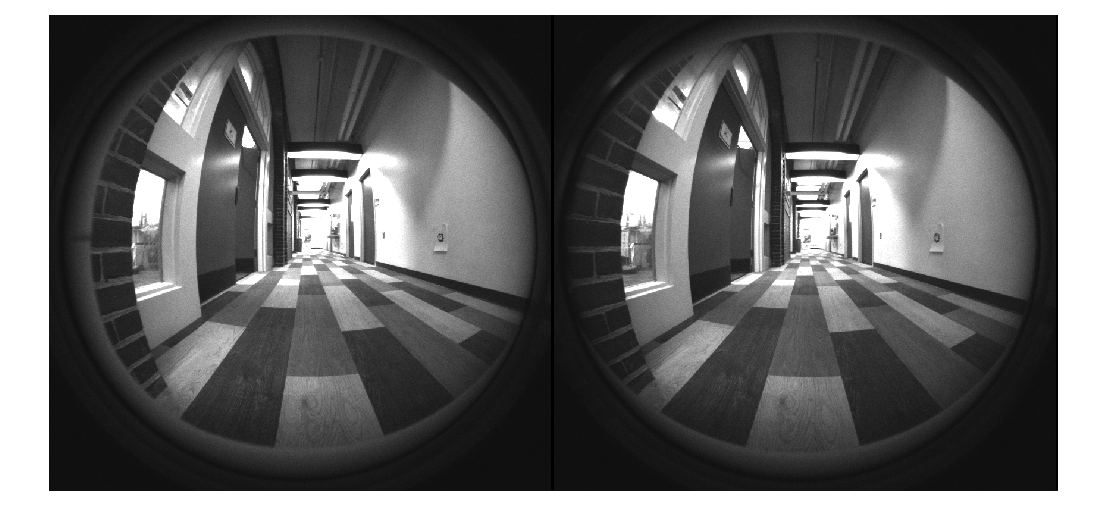
This example uses stereo fisheye images from the WPI Lidar Visual SLAM Dataset [2]. The images have been collected using an Intel® Realsense T265 camera. The size of the data set is 9.7 GB. You can download the data set to a temporary folder using this code.
datasetFolders = ["stereo_fisheye_camera_slam_left_part1","stereo_fisheye_camera_slam_left_part2", ...
                  "stereo_fisheye_camera_slam_right_part1","stereo_fisheye_camera_slam_right_part2"];
datasetURL  = "https://ssd.mathworks.com/supportfiles/shared_nav_vision/data/";
dataFolder = fullfile(tempdir,"wpi_stereo_visual_slam_dataset",filesep);

if ~isfolder(dataFolder)
    mkdir(dataFolder)
end

% Download data
for folder = datasetFolders
    folderFullPath = fullfile(dataFolder,folder);
    if ~isfolder(folderFullPath)
        fileWithExt = folder + ".zip";
        zipFilePath = fullfile(dataFolder,fileWithExt);
        disp("Downloading " + fileWithExt + " (2.4 GB). This download can take a few minutes.")
        websave(folderFullPath,datasetURL + fileWithExt)
        unzip(zipFilePath,dataFolder)
    end
end
Create imageDatastore objects to store the stereo images.
imgFoldersLeft = fullfile(dataFolder,datasetFolders(1:2),"left");
imgFoldersRight = fullfile(dataFolder,datasetFolders(3:4),"right");
imdsLeft = imageDatastore(imgFoldersLeft);
imdsRight = imageDatastore(imgFoldersRight);

% Inspect the first pair of images
currFrameIdx = 1;
fisheyeImg1 = readimage(imdsLeft,currFrameIdx);
fisheyeImg2 = readimage(imdsRight,currFrameIdx);
imshowpair(fisheyeImg1,fisheyeImg2,"montage")
Undistort Fisheye Images
This stereo vSLAM implementation relies on a pinhole camera model, so you must first undistort the fisheye images to remove lens distortion.
Load the stereo fisheye camera parameters, which contain fisheyeIntrinsics objects for the left and right cameras. If you are using your own camera, you can estimate the intrinsic parameters using the Camera Calibrator or Stereo Camera Calibrator app.
leftFisheyeParam = load("t265_left_cameraParams.mat");
rightFisheyeParam = load("t265_right_cameraParams.mat");
leftFisheyeIntrinsics = leftFisheyeParam.t265_left_cameraParams.Intrinsics;
rightFisheyeIntrinsics = rightFisheyeParam.t265_right_cameraParams.Intrinsics;
Undistort the images using the undistortFisheyeImage function. This function transforms the image to a pinhole camera model, and additionally returns the virtual pinhole camera intrinsic parameters virtualIntrinsics, a cameraIntrinsics object.
[pinholeImg1,virtualIntrinsics] = undistortFisheyeImage(fisheyeImg1,leftFisheyeIntrinsics);
[pinholeImg2,~] = undistortFisheyeImage(fisheyeImg2,rightFisheyeIntrinsics);

imshowpair(pinholeImg1,pinholeImg2,"montage")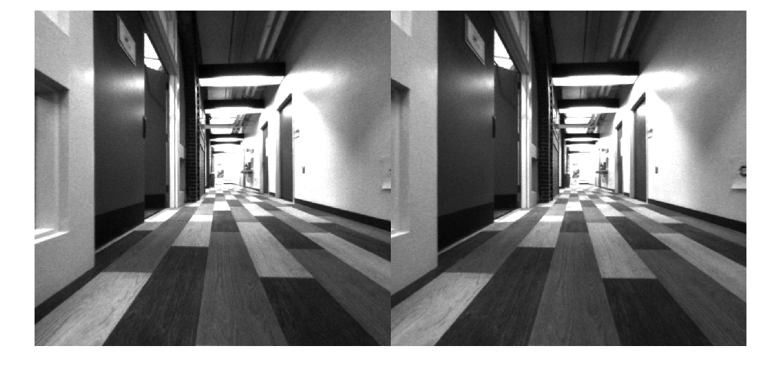
Create Stereo vSLAM Object
Create a stereovslam object with the virtual pinhole model intrinsic parameters found using undistortFisheyeImage. Note that, with this dataset the stereo images are rectified as the stereo cameras are in the same plane. If using the stereo images that are not rectified, you must rectify the images using the rectifyStereoImages function before using the data with a stereovslam object.
You might also need to modify these stereovslam properties based on the video data you intend to use:
SkipMaxFrames─ When tracking from frame to frame is reliable, this property sets the maximum number of frames that the object can skip before the next frame to be a key frame. IncreasingSkipMaxFramesimproves processing speed, but can lead to tracking loss during fast camera motion. Usingstereovslamwith this data set produces a large number of tracked feature points, and thus highly reliable tracking, so you can increase processing speed by setting theSkipMaxFramesproperty to 50 frames, instead of the default 20 frames.DisparityRange─ A two-element array containing the range [minDisparity maxDisparity], in pixels, for stereo reconstruction. The specified range of disparity must cover the minimum and the maximum amount of horizontal shift between the corresponding pixels in the rectified stereo image pairs. Refer to Choosing Range of Disparity for information regarding choosing an appropriate disparity range.LoopClosureThreshold─ The minimum number of matched feature points between loop-closure key frames. The data used in this example creates a large number of features, so increase theLoopClosureThresholdfrom the default 60 to 150 to avoid false positive loop-closure detections.
baseline = 0.064; % meters
numSkipFrames = 50;
disparityRange = [0 64]; % pixels
loopClosureThreshold = 150;
vslam = stereovslam(virtualIntrinsics,baseline,SkipMaxFrames=numSkipFrames,DisparityRange=disparityRange,LoopClosureThreshold=loopClosureThreshold);
Process Stereo Images
The stereovslam object performs visual SLAM for stereo images. The object extracts Oriented FAST and Rotated BRIEF (ORB) features from incrementally read images, and then tracks those features to estimate camera poses, identify key frames, and reconstruct a 3-D environment. The vSLAM algorithm also searches for loop closures using the bag-of-features algorithm, and then optimizes the camera poses using pose graph optimization.
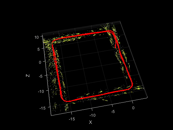
Process each image using the addFrame function. Use the plot function to visualize the estimated trajectory and the 3-D map points.
for i = 1:numel(imdsLeft.Files)
    % Read raw fisheye images from datastore.
    fisheyeImg1 = readimage(imdsLeft,i);
    fisheyeImg2 = readimage(imdsRight,i);

    % Undistort fisheye images.
    pinholeImg1 = undistortFisheyeImage(fisheyeImg1,leftFisheyeIntrinsics);
    pinholeImg2 = undistortFisheyeImage(fisheyeImg2,rightFisheyeIntrinsics);

    % Pass each stereo image frame to the vSLAM algorithm.
    addFrame(vslam,pinholeImg1,pinholeImg2);

    if hasNewKeyFrame(vslam)
        % Display 3-D map points and camera trajectory
        ax = plot(vslam);
    end
end
% Plot intermediate results and wait until all images are processed
while ~isDone(vslam)
    if hasNewKeyFrame(vslam)
        ax = plot(vslam);
    end
end
Compare Trajectory with Ground Truth
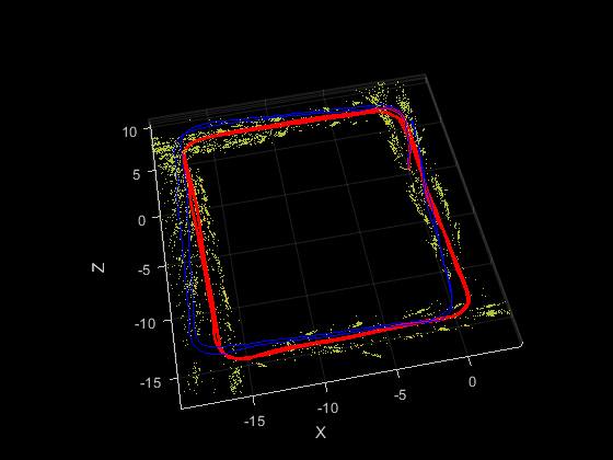
You can compare the optimized camera trajectory with the ground truth to evaluate the accuracy of stereovslam. The comparison can also help tune the properties used by the stereovslam object. In this example, the ground truth baseline trajectory has been generated using highly accurate lidar SLAM. Once you import the ground truth, you can visualize the actual camera trajectory and compare it to the estimated trajectory.
% Retrieve camera poses and key frame IDs
[camPoses,keyFrameIDs] = poses(vslam);
estimatedTrajectory = vertcat(camPoses.Translation);

% Load the ground truth
gTruthData = load("GroundTruthPoses.mat");
actualTrajectory = gTruthData.groundTruthPoses;

% Plot the ground truth trajectory
hold(ax,"on")
plot3(ax,actualTrajectory(:,1),actualTrajectory(:,2),actualTrajectory(:,3),Color="b")
Dense Reconstruction from Stereo Images
Given the refined camera poses, you can perform dense reconstruction from the stereo images corresponding to the key frames.
% Construct reprojection matrix from virtual pinhole-model intrinsics and
% baseline
reprojectionMatrix = [1 0 0 -virtualIntrinsics.PrincipalPoint(1); ...
                      0 1 0 -virtualIntrinsics.PrincipalPoint(2); ...
                      0 0 0 virtualIntrinsics.FocalLength(1); ...
                      0 0 1/baseline 0];

% Create an array of pointCloud objects to store the 3-D world points
% associated with each key frame
numKeyFrames = numel(keyFrameIDs);
ptClouds = repmat(pointCloud(zeros(1,3)),numKeyFrames,1);

numPixels = virtualIntrinsics.ImageSize(1)*virtualIntrinsics.ImageSize(2);

for i = 1:numKeyFrames
    fisheyeImg1 = readimage(imdsLeft,double(keyFrameIDs(i)));
    fisheyeImg2 = readimage(imdsRight,double(keyFrameIDs(i)));

    % Undistort fisheye images.
    pinholeImg1 = undistortFisheyeImage(fisheyeImg1,leftFisheyeIntrinsics);
    pinholeImg2 = undistortFisheyeImage(fisheyeImg2,rightFisheyeIntrinsics);

    % Reconstruct scene from disparity
    disparityMap = disparitySGM(pinholeImg1,pinholeImg2,DisparityRange=disparityRange);
    xyzPoints = reconstructScene(disparityMap,reprojectionMatrix);
    xyzPoints(1:100,:,:) = NaN;

    xyzPoints = reshape(xyzPoints,[numPixels,3]);

    % Get color from the color image
    colors = reshape(pinholeImg1,[numPixels,1]);

    % Remove world points that are behind or too far away from the camera
    validIndex = xyzPoints(:,3) > 0 & xyzPoints(:,3) < 100/reprojectionMatrix(4,3);
    xyzPoints = xyzPoints(validIndex,:);
    colors = colors(validIndex,:);

    % Transform world points to the world coordinates
    xyzPoints  = transformPointsForward(camPoses(i),xyzPoints);
    ptClouds(i) = pointCloud(xyzPoints,Color=repmat(colors,1,3));

    % Downsample the point cloud
    ptClouds(i) = pcdownsample(ptClouds(i),random=0.5);
end

% Concatenate the point clouds
pointCloudsAll = pccat(ptClouds);

% Visualize the point cloud
viewer = pcviewer(pointCloudsAll,VerticalAxis="YDown");

% Navigate to the first camera pose
viewer.CameraUpVector = [0 -1 0];
position = camPoses(1).Translation;
target = [0 0 1 1]*camPoses(1).A';
viewer.CameraPosition = position;
viewer.CameraTarget = target(1:3);
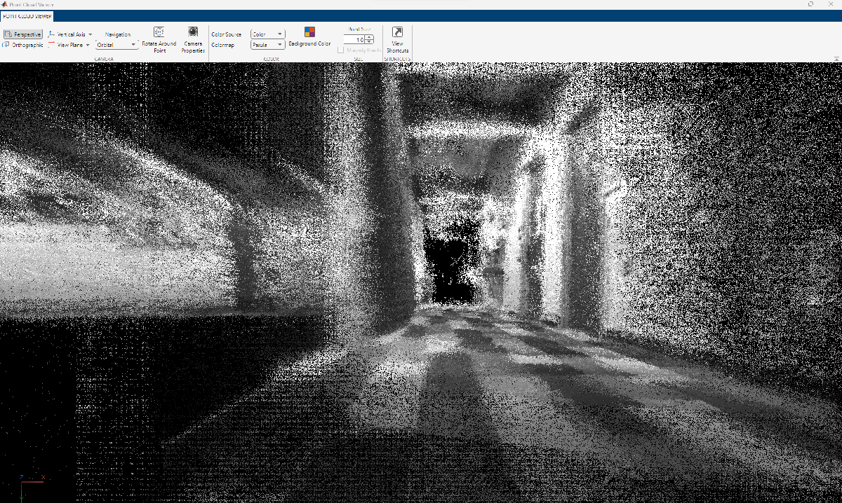
% Move camera to follow estimated trajectory
for i = 1:numKeyFrames
    position = camPoses(i).Translation;
    target = [0 0 1 1]*camPoses(i).A';
    viewer.CameraPosition = position;
    viewer.CameraTarget = target(1:3);
    pause(0.2);
end

Code Generation
You can generate efficient multithreaded C++ code from the stereovslam object, which is suitable for deployment on a host computer or an embedded platform that has all the third-party dependencies, including OpenCV [3] and g2o [4]. For illustrative purposes, in this section, you generate MEX code. For more information about deploying the generated code as a ROS node, see the Build and Deploy Visual SLAM Algorithm with ROS in MATLAB example.
To meet the requirements of MATLAB Coder, you must restructure the code to isolate the algorithm from the visualization code. The algorithmic content is encapsulated in the helperStereoVisualSLAM function, which takes stereo images as the inputs and outputs 3-D world points and camera poses as matrices. The function internally creates a stereovslam object and saves it to a persistent variable called vslam. Note that helperStereoVisualSLAM function does not display the reconstructed 3-D point cloud or the camera poses. The plot function of the stereovslam object has not been designed to generate code because visualization is typically not deployed on embedded systems.
type("helperStereoVisualSLAM.m"); % display function contents
function [xyzPoint, camPoses] = helperStereoVisualSLAM(fisheyeImg1, fisheyeImg2)
%   Copyright 2023 The MathWorks Inc.

%#codegen

persistent vslam xyzPointsInternal camPosesInternal leftFisheyeIntrinsics rightFisheyeIntrinsics

if isempty(vslam)
    % Create fisheye intrinsics objects
    mappingCoeffs = [283.1718 -0.0014 2.7455e-06 -7.9548e-09];
    imageSize = [800 848];
    distortionCenter = [422.0013 383.6340];
    leftFisheyeIntrinsics = fisheyeIntrinsics(mappingCoeffs, imageSize, distortionCenter);

    mappingCoeffs = [278.9833 -0.0011 2.6810e-07 -1.8312e-09];
    distortionCenter = [414.2919 384.3738];
    rightFisheyeIntrinsics = fisheyeIntrinsics(mappingCoeffs, imageSize, distortionCenter);

    % Find virtual pinhole model intrinsics.
    [~, virtualIntrinsics] = undistortFisheyeImage(fisheyeImg1, leftFisheyeIntrinsics);

    % Create stereovslam object.
    baseline = 0.064; % meters
    numSkipFrames  = 50;
    disparityRange = [0 64]; % pixels
    loopClosureThreshold = 150;
    vslam = stereovslam(virtualIntrinsics, baseline, SkipMaxFrames=numSkipFrames, DisparityRange=disparityRange, LoopClosureThreshold=loopClosureThreshold);
end

% Undistort fisheye images.
pinholeImg1 = undistortFisheyeImage(fisheyeImg1, leftFisheyeIntrinsics);
pinholeImg2 = undistortFisheyeImage(fisheyeImg2, rightFisheyeIntrinsics);

% Process each stereo image frame.
addFrame(vslam, pinholeImg1, pinholeImg2);

% Get 3-D map points and camera poses.
if isempty(xyzPointsInternal) || hasNewKeyFrame(vslam)
    xyzPointsInternal = mapPoints(vslam);
    camPosesInternal = poses(vslam);
end

xyzPoint = xyzPointsInternal;

% Convert camera poses to homogeneous transformation matrices
camPoses = cat(3, camPosesInternal.A);
You can compile the helperStereoVisualSLAM function into a MEX file by using the codegen command. Note that the generated MEX file has the same name as the original MATLAB file with _mex appended, unless you use the -o option to specify the name of the executable.
compileTimeInputs = {coder.typeof(fisheyeImg1),coder.typeof(fisheyeImg2)};

codegen helperStereoVisualSLAM -args compileTimeInputs
Code generation successful.
Process the image data frame-by-frame using the MEX file.
% Process each image frame
for i=1:numel(imdsLeft.Files)
    [xyzPoints,camPoses] = helperStereoVisualSLAM_mex(readimage(imdsLeft,i),readimage(imdsRight,i));
end
Implementations for Other Sensors
You can find more details about the implementation of monocular and RGB-D visual SLAM on the monovslam and rgbdvslam object pages, respectively. Alternatively, you can integrate the camera with an IMU sensor to recover the actual scale using the visual-inertial SLAM algorithm. These examples demonstrate some of these implementations:
Reference
[1] Mur-Artal, Raul, J. M. M. Montiel, and Juan D. Tardos. “ORB-SLAM: A Versatile and Accurate Monocular SLAM System.” IEEE Transactions on Robotics 31, no. 5 (October 2015): 1147–63. https://doi.org/10.1109/TRO.2015.2463671.
[2] WPI Lidar Visual SLAM Dataset, GitHub repository, https://github.com/WPI-APA-Lab/WPI-Lidar-Visual-SLAM-Dataset
[3] “OpenCV: OpenCV Modules. ”https://docs.opencv.org/4.7.0/.
[4] Kümmerle, Rainer, Giorgio Grisetti, Hauke Strasdat, Kurt Konolige, and Wolfram Burgard. “G2o: A General Framework for Graph Optimization.” In 2011 IEEE International Conference on Robotics and Automation, 3607–13, 2011. https://doi.org/10.1109/ICRA.2011.5979949.