Enabled Subsystem
Subsystem whose execution is enabled by external input
Libraries:
Simulink /
Ports & Subsystems
HDL Coder /
Ports & Subsystems
Description
Enabled Subsystem block is a Subsystem block that executes based on an external signal when the signal has a positive value. An enabled subsystem executes when an external signal at the Enable port crosses zero from the negative to positive direction.
The Enabled Subsystem block is configured by placing an Enable block inside a Subsystem block. Execution of the enabled subsystem is controlled by the Enable port of the Enabled Subsystem block.

Use Enabled Subsystem block to model:
discontinuities in the execution of the blocks inside the subsystem. For example, the counter circuit in Counters Using Conditionally Executed Subsystems increments while the subsystem is enabled and holds its output when the subsystem is disabled.
multiple enabled subsystems that execute when those subsystems receive positive control signal at the Enable ports. For example, see Implement Control Algorithm Using Enabled Subsystem, Control Block States and Output of Enabled Subsystem and Merging Signals.
Examples
Implement Control Algorithm Using Enabled Subsystem
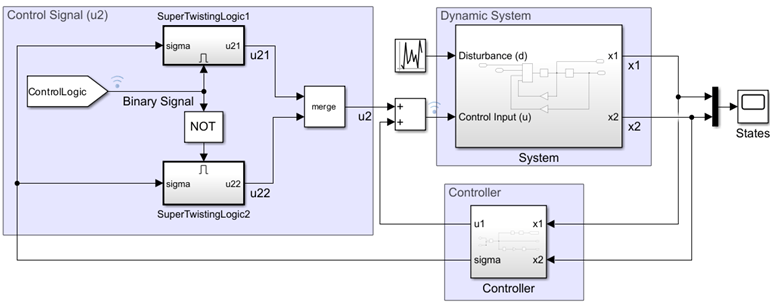
Use an enabled subsystems to implement a control algorithm based on a binary logic signal. The enabled subsystems execute when the binary signal has a positive value and implements the control algorithm. In this example, the super-twisting control algorithm is used to stabilize an unstable dynamic system. The super-twisting algorithm is one of the well known sliding mode control techniques for its robust performance.

Control Block States and Output of Enabled Subsystem
Reset or hold states of blocks inside an Enabled Subsystem block when the subsystem is disabled and how to control the subsystem output. In this example, you see four different combinations of state and output value configurations for both discrete and continuous control signals. When the enabled subsystem is disabled, the combinations work as follows:
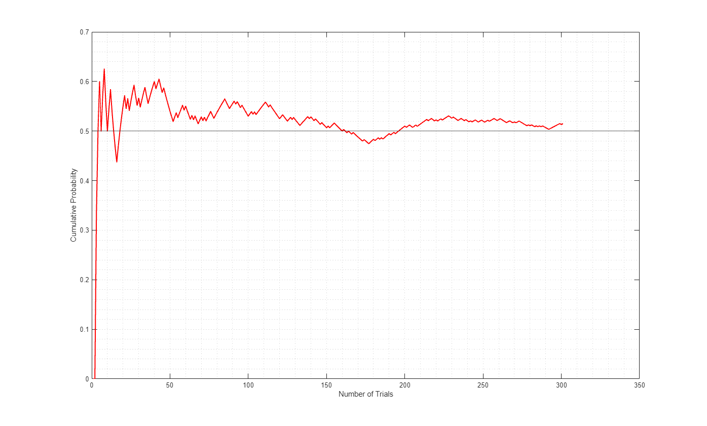
Exploring Law of Large Numbers using MATLAB System Block
Use MATLAB System blocks to illustrate the law of large numbers in Simulink.
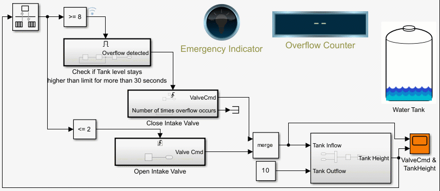
Counters Using Conditionally Executed Subsystems
Implement counters using Enabled and Triggered subsystems. In this example, the model sldemo_counters controls flow of water into a tank and uses a counter to count the number of times overflow occurs, where overflow occurs when the water level in the tank is 8 meters or more for 30 seconds or more.
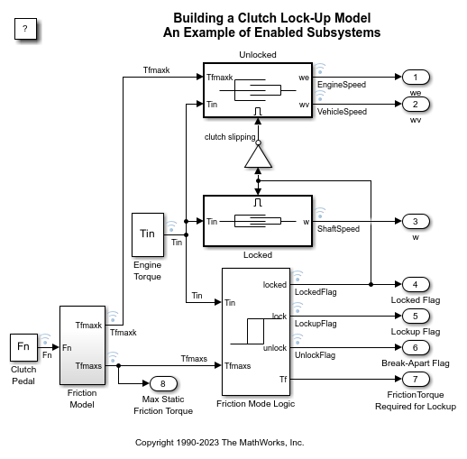
Building a Clutch Lock-Up Model
Use Simulink® to model and simulate a rotating clutch system. Although modeling a clutch system is difficult because of topological changes in the system dynamics during lockup, this example shows how enabled subsystem can easily handle such problems. We illustrate how to employ important Simulink modeling concepts in the creation of the clutch simulation. Designers can apply these concepts to many models with strong discontinuities and constraints that may change dynamically.
Ports
Input
Signal input to a Subsystem block, specified as a scalar, vector, or matrix. Placing an Inport block in a subsystem adds an external input port to the Subsystem block. The port label matches the name of the Inport block.
Use Inport blocks to receive signals from the local environment.
Data Types: half | single | double | int8 | int16 | int32 | int64 | uint8 | uint16 | uint32 | uint64 | Boolean | fixed point | enumerated | bus | image
An Enable block in a subsystem adds an external input port to the Subsystem block and makes the block an Enabled Subsystem block.
Data Types: single | double | int8 | int16 | int32 | int64 | uint8 | uint16 | uint32 | uint64 | Boolean | fixed point
Output
Signal output from a Subsystem block, returned as a scalar, vector, or matrix. Placing an Outport block in a subsystem adds an external output port to the Subsystem block. The port label matches the name of the Outport block.
Use Outport blocks to send signals to the local environment.
Data Types: half | single | double | int8 | int16 | int32 | int64 | uint8 | uint16 | uint32 | uint64 | Boolean | fixed point | enumerated | bus | image
Parameters
To edit block parameters interactively, use the Property Inspector. From the Simulink® Toolstrip, on the Simulation tab, in the Prepare gallery, select Property Inspector.
Main
Select how to display port labels on the Subsystem block icon.
none— Do not display port labels.FromPortIcon— If the corresponding port icon displays a signal name, display the signal name on the Subsystem block. Otherwise, display the port block name or the port number if the block name is a default name.FromPortBlockName— Display the name of the corresponding port block on the Subsystem block.SignalName— If the signal connected to the port is named, display the name of the signal on the Subsystem block. Otherwise, display the name of the corresponding port block.
For port label editing on Subsystem blocks, see Edit Port Labels on Subsystem Blocks.
Programmatic Use
To set the block parameter value programmatically, use
the set_param function.
| Parameter: | ShowPortLabels |
| Values: | 'FromPortIcon' (default) | 'FromPortBlockName' | 'SignalName' | 'none' |
Control user access to the contents of the subsystem.
ReadWrite— Enable opening and modification of subsystem contents.ReadOnly— Enable opening but not modification of the subsystem. If the subsystem resides in a block library, you can create and open links to the subsystem and can make and modify local copies of the subsystem but cannot change the permissions or modify the contents of the original library instance.NoReadOrWrite— Disable opening or modification of subsystem. If the subsystem resides in a library, you can create links to the subsystem in a model but cannot open, modify, change permissions, or create local copies of the subsystem.
You do not receive a response if you attempt to view the contents of a subsystem whose Read/Write permissions parameter is set to NoReadOrWrite. For example, when double-clicking such a subsystem, the software does not open the subsystem and does not display any messages.
Programmatic Use
To set the block parameter value programmatically, use
the set_param function.
| Parameter: | Permissions |
| Values: | 'ReadWrite' (default) | 'ReadOnly' | 'NoReadOrWrite' |
Enter the name of a function to be called if an error occurs while the software executes the subsystem.
The software passes two arguments to the function: the handle of the subsystem and a character vector that specifies the error type. If no function is specified, the software displays a generic error message if executing the subsystem causes an error.
Programmatic Use
To set the block parameter value programmatically, use
the set_param function.
| Parameter: | ErrorFcn |
| Values: | '' (default) | function name in quotes |
| Data Types: | char | string |
Select whether to resolve names of workspace variables referenced by this subsystem.
For more information, see Symbol Resolution and Symbol Resolution Process.
All— Resolve all names of workspace variables used by this subsystem, including those used to specify block parameter values and Simulink data objects (for example,Simulink.Signalobjects).ExplicitOnly— Resolve only names of workspace variables used to specify block parameter values, data store memory (where no block exists), signals, and states marked as “must resolve”.None— Do not resolve any workspace variable names.
Programmatic Use
To set the block parameter value programmatically, use
the set_param function.
| Parameter: | PermitHierarchicalResolution |
| Values: | 'All' (default) | 'ExplicitOnly' | 'None' |
Select this parameter to display the reinitialize event ports. Clear this parameter to remove the ports.
Dependencies
To enable this parameter, select Treat as atomic unit.
Programmatic Use
To set the block parameter value programmatically, use
the set_param function.
| Parameter: | ShowSubsystemReinitializePorts |
| Values: | 'off' (default) | 'on' |
Atomic subsystems can create artificial algebraic loops. To minimize the occurrence of artificial algebraic loops that involve this subsystem, enable this parameter.
off— The software does not try to eliminate artificial algebraic loops that involve this subsystem.on— The software tries to eliminate artificial algebraic loops that involve this subsystem.
For more information, see Minimize Artificial Algebraic Loop Occurrences.
Dependencies
To enable this parameter, select Treat as atomic unit.
Programmatic Use
To set the block parameter value programmatically, use
the set_param function.
| Parameter: | MinAlgLoopOccurrences |
| Values: | "off" (default) | "on" |
Code Generation
Parameters on the Code Generation tab require a Simulink Coder™ or Embedded Coder® license.
Select the code format to be generated for an atomic (nonvirtual) subsystem.
Auto— The software chooses the optimal format for you based on the type and number of instances of the subsystem that exist in the model.Inline— The software inlines the subsystem unconditionally.Nonreusable function— If Filename options is set toAuto, the software packages separate functions in the model file. If File name options is set toUse subsystem name,Use function name, orUser specifiedusing different filenames, the software packages separate functions in separate files.Subsystems with this setting generate functions that might have arguments depending on the Function interface parameter setting. You can name the generated function and file using parameters Function name and File name (no extension), respectively. These functions are not reentrant.
Reusable function— The software generates a function with arguments that allows reuse of subsystem code when a model includes multiple instances of the subsystem.This option also generates a function with arguments that allows subsystem code to be reused in the generated code of a model reference hierarchy that includes multiple instances of a subsystem across referenced models. In this case, the subsystem must be in a library.
For more information, see:
Generate Inlined Subsystem Code (Simulink Coder)
Generate Subsystem Code as Separate Function and Files (Simulink Coder)
Generate Reusable Code from Library Subsystems Shared Across Models (Simulink Coder)
The default value depends on the block configuration. For example, the default
value for the Subsystem block is Auto.
The default value for the CodeReuseSubsystem block is
Reusable function.
Tips
When you want multiple instances of a subsystem to be represented as one reusable function, you can designate each one of them as
Autoor asReusable function. Using one or the other is best, as using both creates two reusable functions, one for each designation. The outcomes of these choices differ only when reuse is not possible. SelectingAutodoes not allow control of the function or filename for the subsystem code.The
Reusable functionandAutooptions both try to determine if multiple instances of a subsystem exist and if the code can be reused. The difference between the behavior of each option is that when reuse is not possible:Autoyields inlined code, or if circumstances prohibit inlining, separate functions for each subsystem instance.Reusable functionyields a separate function with arguments for each subsystem instance in the model.
If you select
Reusable functionwhile your generated code is under source control, set File name options toUse subsystem name,Use function name, orUser specified. Otherwise, the names of your code files change whenever you modify your model, which prevents source control on your files.If you select an option other than
AutoorInlineand the model configuration parameter States, the code generator produces separate output and update methods. The code generator does not take into account the Combine output and update methods for code generation and simulation specification.
Dependencies
This parameter requires a Simulink Coder license for code generation.
To enable this parameter, select Treat as atomic unit.
Programmatic Use
To set the block parameter value programmatically, use
the set_param function.
| Parameter: | RTWSystemCode |
| Values: | 'Auto' | 'Inline' | 'Nonreusable function' | 'Reusable function' |
Select how the software names the function it generates for the subsystem.
If you have an Embedded Coder license, you can control function names with options on the Configuration Parameter Code Generation > Identifiers pane.
Auto— Assign a unique function name using the default naming convention,model_subsystem()modelis the name of the model andsubsystemis the name of the subsystem, or that of an identical one when code is being reused.If you select
Reusable functionfor the Function packaging parameter and a model reference hierarchy contains multiple instances of the reusable subsystem, in order to generate reusable code for the subsystem, Function name options must be set toAuto.Use subsystem name— Use the subsystem name as the function name. By default, the function name uses the naming conventionmodel_subsystemWhen a subsystem is in a library block and the subsystem parameter Function packaging is set to
Reusable function, if you set theUse subsystem nameoption, the code generator uses the name of the library block for the subsystem function name and filename.User specified— Enable the Function name field. Enter any legal C or C++ function name, which must be unique.
For more information, see Generate Subsystem Code as Separate Function and Files (Simulink Coder).
The default value depends on the block configuration. For example, the default
value for the Subsystem block is Auto.
The default value for the CodeReuseSubsystem block is
Use subsystem name.
Dependencies
This parameter requires a Simulink Coder license.
To enable this parameter, set Function packaging to
Nonreusable functionorReusable function.
Programmatic Use
To set the block parameter value programmatically, use
the set_param function.
| Parameter: | RTWFcnNameOpts |
| Values: | 'Auto' | 'Use subsystem name' | 'User specified' |
Specify a unique, valid C or C++ function name for subsystem code.
Use this parameter if you want to give the function a specific name instead of allowing the Simulink Coder code generator to assign its own autogenerated name or use the subsystem name. For more information, see Generate Subsystem Code as Separate Function and Files (Simulink Coder).
Dependencies
This parameter requires a Simulink Coder license.
To enable this parameter, set Function name options to
User specified.
Programmatic Use
To set the block parameter value programmatically, use
the set_param function.
| Parameter: | RTWFcnName |
| Values: | '' (default) | function name in quotes |
| Data Types: | char | string |
Select how the software names the separate file for the function it generates for the subsystem.
Auto— Depending on the configuration of the subsystem and how many instances are in the model,Autoyields different results.If the code generator does not generate a separate file for the subsystem, the subsystem code is generated within the code module generated from the subsystem parent system. If the subsystem parent is the model itself, the subsystem code is generated within
model.cmodel.cppIf you select
Reusable functionfor the Function packaging parameter and your generated code is under source control, consider specifying a File name options value other thanAuto. This prevents the generated filename from changing due to unrelated model modifications, which is problematic for using source control to manage configurations.If you select
Reusable functionfor the Function packaging parameter and a model reference hierarchy contains multiple instances of the reusable subsystem, in order to generate reusable code for the subsystem, File name options must be set toAuto.
Use subsystem name— The code generator generates a separate file, using the subsystem (or library block) name as the filename.When File name options is set to
Use subsystem name, the subsystem filename is mangled if the model contains Model blocks, or if a model reference target is being generated for the model. In these situations, the filename for the subsystem consists of the subsystem name prefixed by the model name.Use function name— The code generator uses the function name specified by Function name options as the filename.User specified— This option enables the File name (no extension) text entry field. The code generator uses the name you enter as the filename. Enter any filename, but do not include the.cor.cpp(or any other) extension. This filename need not be unique.While a subsystem source filename need not be unique, you must avoid giving nonunique names that result in cyclic dependencies. For example,
sys_a.hincludessys_b.h,sys_b.hincludessys_c.h, andsys_c.hincludessys_a.h.
The default value depends on the block configuration. For example, the default
value for the Subsystem block is Auto.
The default value for the CodeReuseSubsystem block is
Use function name.
Dependencies
This parameter requires a Simulink Coder license.
To enable this parameter, set Function packaging to
Nonreusable functionorReusable function.
Programmatic Use
To set the block parameter value programmatically, use
the set_param function.
| Parameter: | RTWFileNameOpts |
| Values: | 'Auto' | 'Use subsystem name' | 'Use function name' | 'User specified' |
The filename that you specify does not have to be unique. However, avoid giving
non-unique names that result in cyclic dependencies. For example,
sys_a.h includes sys_b.h,
sys_b.h includes sys_c.h, and
sys_c.h includes sys_a.h.
For more information, see Generate Subsystem Code as Separate Function and Files (Simulink Coder).
Dependencies
This parameter requires a Simulink Coder license.
To enable this parameter, set File name options to
User specified.
Programmatic Use
To set the block parameter value programmatically, use
the set_param function.
| Parameter: | RTWFileName |
| Values: | '' (default) | filename in quotes |
| Data Types: | char | string |
Select how to use arguments with the generated function.
void_void— Generate a function without arguments and pass data as global variables. For example:void subsystem_function(void)
Allow arguments (Optimized)— Generate a function that uses arguments instead of passing data as global variables. This specification reduces global RAM. This option might reduce code size and improve execution speed and enable the code generator to apply additional optimizations. For example:void subsystem_function(real_T rtu_In1, real_T rtu_In2, real_T *rty_Out1)In some cases, when generating optimized code, the code generator might not generate a function that has arguments.
Allow arguments (Match graphical interface)— Generate a function interface that uses arguments that match the Subsystem graphical block interface. The generated function interface is predictable and does not change. A predictable interface can be useful for debugging and testing your code and integrating with external applications. For example, if a model has two Inport blocks and two Outport blocks, then the generated function interface is:void subsystem_function(real_T rtu_In1, real_T rtu_In2, real_T *rty_Out1, real_T *rty_Out2)
For more information, see:
Reduce Global Variables in Nonreusable Subsystem Functions (Embedded Coder)
Generate Predictable Function Interface to Match Graphical Block Interface (Embedded Coder)
Generate Modular Function Code for Nonvirtual Subsystems (Embedded Coder)
Dependencies
This parameter requires an Embedded Coder license and an ERT-based system target file.
To enable this parameter, set Function packaging to
Nonreusable function.
Programmatic Use
To set the block parameter value programmatically, use
the set_param function.
| Parameter: | FunctionInterfaceSpec |
| Values: | 'void_void' (default) | 'Allow arguments (Optimized)' | 'Allow arguments (Match graphical interface)' |
Generate subsystem function code in which the internal data for an atomic subsystem is separated from its parent model and is owned by the subsystem.
off— Do not generate subsystem function code in which the internal data for an atomic subsystem is separated from its parent model and is owned by the subsystem.on— Generate subsystem function code in which the internal data for an atomic subsystem is separated from its parent model and is owned by the subsystem. The subsystem data structure is declared independently from the parent model data structures. A subsystem with separate data has its own block I/O andDWorkdata structure. As a result, the generated code for the subsystem is easier to trace and test. The data separation also tends to reduce the maximum size of global data structures throughout the model, because they are split into multiple data structures.
For details on how to generate modular function code for an atomic subsystem, see Generate Modular Function Code for Nonvirtual Subsystems (Embedded Coder).
For details on how to apply memory sections to atomic subsystems, see Override Default Memory Placement for Subsystem Functions and Data (Embedded Coder).
Dependencies
This parameter requires an Embedded Coder license and an ERT-based system target file.
To enable this parameter, set Function packaging to
Nonreusable function.
Programmatic Use
To set the block parameter value programmatically, use
the set_param function.
| Parameter: | FunctionWithSeparateData |
| Values: | 'off' (default) | 'on' |
Select how the software applies memory sections to the subsystem initialization and termination functions.
Inherit from model— Apply the root model memory sections to the subsystem function code.Default— Do not apply memory sections to the subsystem system code, overriding any model-level specification.Apply one of the model memory sections to the subsystem.
Tips
The possible values vary depending on what, if any, package of memory sections you have set for the model configuration. See Control Data and Function Placement in Memory by Inserting Pragmas (Embedded Coder) and Model Configuration Parameters: Code Generation (Simulink Coder).
If you have not configured the model with a package,
Inherit from
									model
is the only available value. Otherwise, the list includesDefaultand all memory sections the model package contains.These options can be useful for overriding the model memory section settings for the given subsystem. For details on how to apply memory sections to atomic subsystems, see Override Default Memory Placement for Subsystem Functions and Data (Embedded Coder).
Dependencies
This parameter requires an Embedded Coder license and an ERT-based system target file.
To enable this parameter, set Function packaging to
Nonreusable functionorReusable function.
Programmatic Use
To set the block parameter value programmatically, use
the set_param function.
| Parameter: | RTWMemSecFuncInitTerm |
| Values: | 'Inherit from model' (default) | 'Default' | model memory section in quotes |
Select how Embedded Coder applies memory sections to the subsystem execution functions.
Inherit from model— Apply the root model memory sections to the subsystem function code.Default— Do not apply memory sections to the subsystem system code, overriding any model-level specification.Apply one of the model memory sections to the subsystem.
Tips
The possible values vary depending on what, if any, package of memory sections you have set for the model configuration. See Control Data and Function Placement in Memory by Inserting Pragmas (Embedded Coder) and Model Configuration Parameters: Code Generation (Simulink Coder).
If you have not configured the model with a package,
Inherit from
									model
is the only available value. Otherwise, the list includesDefaultand all memory sections the model package contains.These options can be useful for overriding the model memory section settings for the given subsystem. For details on how to apply memory sections to atomic subsystems, see Override Default Memory Placement for Subsystem Functions and Data (Embedded Coder).
Dependencies
This parameter requires an Embedded Coder license and an ERT-based system target file.
To enable this parameter, set Function packaging to
Nonreusable functionorReusable function.
Programmatic Use
To set the block parameter value programmatically, use
the set_param function.
| Parameter: | RTWMemSecFuncExecute |
| Values: | 'Inherit from model' (default) | 'Default' | model memory section in quotes |
Select how the software applies memory sections to the subsystem constants.
Inherit from model— Apply the root model memory sections to the subsystem data.Default— Do not apply memory sections to the subsystem data, overriding any model-level specification.Apply one of the model memory sections to the subsystem.
Tips
The memory section that you specify applies to the corresponding global data structures in the generated code. For basic information about the global data structures generated for atomic subsystems, see Standard Data Structures (Simulink Coder).
The possible values vary depending on what, if any, package of memory sections you have set for the model configuration. See Control Data and Function Placement in Memory by Inserting Pragmas (Embedded Coder).
If you have not configured the model with a package,
Inherit from modelis the only available value. Otherwise, the list includesDefaultand all memory sections the model package contains.These options can be useful for overriding the model memory section settings for the given subsystem. For details on how to apply memory sections to atomic subsystems, see Override Default Memory Placement for Subsystem Functions and Data (Embedded Coder).
Dependencies
This parameter requires an Embedded Coder license and an ERT-based system target file.
To enable this parameter, set Function packaging to
Nonreusable functionand select the Function with separate data parameter.
Programmatic Use
To set the block parameter value programmatically, use
the set_param function.
| Parameter: | RTWMemSecDataConstants |
| Values: | 'Inherit from model' (default) | 'Default' | model memory section in quotes |
Select how the software applies memory sections to the subsystem internal data.
Inherit from model— Apply the root model memory sections to the subsystem data.Default— Do not apply memory sections to the subsystem data, overriding any model-level specification.Apply one of the model memory sections to the subsystem.
Tips
The memory section that you specify applies to the corresponding global data structures in the generated code. For basic information about the global data structures generated for atomic subsystems, see Standard Data Structures (Simulink Coder).
The possible values vary depending on what, if any, package of memory sections you have set for the model configuration. See Control Data and Function Placement in Memory by Inserting Pragmas (Embedded Coder).
If you have not configured the model with a package,
Inherit from modelis the only available value. Otherwise, the list includesDefaultand all memory sections the model package contains.These options can be useful for overriding the model memory section settings for the given subsystem. For details on how to apply memory sections to atomic subsystems, see Override Default Memory Placement for Subsystem Functions and Data (Embedded Coder).
Dependencies
This parameter requires an Embedded Coder license and an ERT-based system target file.
To enable this parameter, set Function packaging to
Nonreusable functionand select the Function with separate data parameter.
Programmatic Use
To set the block parameter value programmatically, use
the set_param function.
| Parameter: | RTWMemSecDataInternal |
| Values: | 'Inherit from model' (default) | 'Default' | model memory section in quotes |
Select how the software applies memory sections to the subsystem parameters.
Inherit from model— Apply the root model memory sections to the subsystem function code.Default— Do not apply memory sections to the subsystem system code, overriding any model-level specification.Apply one of the model memory sections to the subsystem.
Tips
The memory section that you specify applies to the corresponding global data structure in the generated code. For basic information about the global data structures generated for atomic subsystems, see Standard Data Structures (Simulink Coder).
The possible values vary depending on what, if any, package of memory sections you have set for the model configuration. See Control Data and Function Placement in Memory by Inserting Pragmas (Embedded Coder).
If you have not configured the model with a package,
Inherit from modelis the only available value. Otherwise, the list includesDefaultand all memory sections the model package contains.These options can be useful for overriding the model memory section settings for the given subsystem. For details on how to apply memory sections to atomic subsystems, see Override Default Memory Placement for Subsystem Functions and Data (Embedded Coder).
Dependencies
This parameter requires an Embedded Coder license and an ERT-based system target file.
To enable this parameter, set Function packaging to
Nonreusable functionand select the Function with separate data parameter.
Programmatic Use
To set the block parameter value programmatically, use
the set_param function.
| Parameter: | RTWMemSecDataParameters |
| Values: | 'Inherit from model' (default) | 'Default' | model memory section in quotes |
Subsystem Reference
Specify the subsystem file you want to reference. For information about subsystem references, see Create and Use Referenced Subsystems in Models.
Dependencies
To access this parameter, in the Subsystem Reference section, click Convert.
For more information on how to convert a subsystem to a referenced subsystem, see Convert Between Subsystems and Referenced Subsystems.
Programmatic Use
To set the block parameter value programmatically, use
the set_param function.
| Parameter: | ReferencedSubsystem |
| Values: | '' (default) | subsystem filename in quotes |
| Data Types: | char | string |
Block Characteristics
Extended Capabilities
Actual code generation support depends on block implementation.
HDL Coder™ provides additional configuration options that affect HDL implementation and synthesized logic.
When using enabled subsystems in models targeted for HDL code generation, it is good practice to consider the following:
For synthesis results to match Simulink results, the Enable port must be driven by registered logic (with a synchronous clock) on the FPGA.
Put unit delays on Enabled Subsystem output signals. Doing so prevents the code generator from inserting extra bypass registers in the HDL code.
Enabled subsystems can affect synthesis results in the following ways:
In some cases, the system clock speed can drop by a small percentage.
Generated code uses more resources, scaling with the number of enabled subsystem instances and the number of output ports per subsystem.
| Architecture | Description |
|---|---|
Module (default) | Generate code for the subsystem and the blocks within the subsystem. |
BlackBox | Generate a black box interface. The generated HDL code includes only the input/output port definitions for the subsystem. Therefore, you can use a subsystem in your model to generate an interface to existing, manually written HDL code. The black-box interface generation for subsystems is similar to the Model block interface generation without the clock signals. |
| Remove the subsystem from the generated code. You can use the subsystem in simulation, however, treat it as a “no-op” in the HDL code. |
| General | |
|---|---|
| AdaptivePipelining | Automatic pipeline insertion based on the synthesis tool, target frequency, and
multiplier word-lengths. The default is |
| ClockRatePipelining | Insert pipeline registers at a faster clock rate instead of the slower data rate. The
default is |
| ConstrainedOutputPipeline | Number of registers to place at
the outputs by moving existing delays within your design. Distributed
pipelining does not redistribute these registers. The default is
|
| DistributedPipelining | Pipeline register distribution,
or register retiming. The default is |
| FlattenHierarchy | Remove subsystem hierarchy from generated HDL code. The default
is |
| InputPipeline | Number of input pipeline stages
to insert in the generated code. Distributed pipelining and constrained
output pipelining can move these registers. The default is
|
| OutputPipeline | Number of output pipeline stages
to insert in the generated code. Distributed pipelining and constrained
output pipelining can move these registers. The default is
|
| SharingFactor | Number of functionally equivalent resources to map to a single shared resource. The default is 0. See also Resource Sharing (HDL Coder). |
| StreamingFactor | Number of parallel data paths, or vectors, that are time multiplexed to transform into serial, scalar data paths. The default is 0, which implements fully parallel data paths. See also Streaming (HDL Coder). |
| SynthesisAttributes |
Specifies the synthesis attributes for the blocks and block output signals in the model. The generated HDL code contains these attributes. For more information, see SynthesisAttributes (HDL Coder). |
If this block is not the DUT, the block property settings in the Target
Specification tab are ignored. In the HDL Workflow Advisor, if you use the
IP Core Generation workflow, these target specification block
property values are saved with the model. If you specify these target specification block
property values using hdlset_param, when you open HDL Workflow Advisor,
the fields are populated with the corresponding values.
| Target Specification | |
|---|---|
| AdditionalTargetInterfaces |
Additional target interfaces, specified as a character vector. To save this block property on the model, in the Set Target Interface task of the IP Core Generation workflow, corresponding to the DUT ports that you want to add more interfaces, select Add more.... You can then add more interfaces in the Add New Target Interfaces dialog box. Specify the type of interface, number of additional interfaces, and a unique name for each additional interface. Values: Example:
|
| ProcessorFPGASynchronization | Processor/FPGA synchronization mode, specified as a character vector. To save this block property on the model, specify the Processor/FPGA Synchronization in the Set Target Interface task of the IP Core Generation workflow. Values: Example: |
| TestPointMapping | To save this block property on the model, specify the mapping of test point ports to target platform interfaces in the Set Target Interface task of the IP Core Generation workflow. Values: Example: |
| TunableParameterMapping | To save this block property on the model, specify the mapping of tunable parameter ports to target platform interfaces in the Set Target Interface task of the IP Core Generation workflow. Values: Example: |
| WriteRegisterReadback | To save this block property on the model, specify whether you want to enable readback on write registers such as AXI4 subordinate interface in the Generate RTL Code and IP Core task of the IP Core Generation workflow. To learn more, see Model Design for AXI4 Register Interface Generation (HDL Coder). Values: |
| AXI4SubordinateIDWidth |
To save this block property on the model, specify the number of AXI manager interfaces that you want to connect the DUT IP core to by using the AXI4 Subordinate ID Width setting in the Generate RTL Code and IP Core task of the IP Core Generation workflow. To learn more, see Define Multiple AXI Master Interfaces in Reference Designs to Access DUT AXI4 Subordinate Interface (HDL Coder). Values: |
| RegisterInterfaceReadPipeline |
To save this block property on the model, Specify the number of pipeline stages to insert in the read address decoder path by using the Register interface read pipeline setting in the Generate RTL Code and IP Core task of the IP Core Generation workflow. To learn more, see Model Design for AXI4 Register Interface Generation (HDL Coder). Values: |
| GenerateDefaultRegisterInterface | To save this block property on the model, specify whether you want to disable generation of default register interfaces such as AXI4 subordinate interfaces in the Generate RTL Code and IP Core task of the IP Core Generation workflow. Values: |
| IPCoreAdditionalFiles | Verilog®, SystemVerilog, or VHDL® files for black boxes in your design. Specify the full path to each file, and separate file names with a semicolon (;). You can set this property in the HDL Workflow Advisor, in the Additional source files field. Values: Example: |
| IPCoreName | IP core name, specified as a character vector. You can set this property in the HDL Workflow Advisor, in the IP core name field. If this property is set to the default value, the HDL Workflow Advisor constructs the IP core name based on the name of the DUT. Values: Example: |
| IPCoreVersion | IP core version number, specified as a character vector. You can set this property in the HDL Workflow Advisor, in the IP core version field. If this property is set to the default value, the HDL Workflow Advisor sets the IP core version. Values: Example: |
| IPDataCaptureBufferSize |
FPGA Data Capture buffer size, specified as a character vector. Use FPGA Data Capture to observe signals in a design when running on an FPGA. The buffer size uses values that are 128*2^n, where n is an integer. By default, the buffer size is 128 (n=0). The maximum value of n is 13, which means that the maximum value for buffer size is 1048576 (=128*2^13). Values: Example: |
| IPCoreVendorName |
IP core vendor name, specified as a character vector. You can set this property in the HDL Workflow Advisor by entering a value in the IP core vendor name field. If this property is set to the default value, the HDL Workflow Advisor sets the vendor name to the domain name of your host machine. The vendor name must not start with a numeric character (for example,
Values: Example: |
HDL Coder supports HDL code generation for enabled subsystems that meet the following conditions:
The subsystem is not both triggered and enabled.
The enable signal is a scalar.
The input datatype for the enable signal is boolean.
If the output of the subsystem is a bus then Initial condition of the outport must be 0.
All inputs and outputs of the enabled subsystem (including the enable signal) run at the same rate.
The Show output port parameter of the Enable block is set to
Off.The States when enabling parameter of the Enable block is set to
held(i.e., the Enable block does not reset states when enabled).The Output when disabled parameter for the enabled subsystem output ports is set to
held(i.e., the enabled subsystem does not reset output values when disabled).If the DUT contains the following blocks,
RAMArchitectureis set toWithClockEnable:Dual Port RAM
Simple Dual Port RAM
Single Port RAM
The enabled subsystem does not contain the following blocks:
CIC Decimation
CIC Interpolation
FIR Decimation
FIR Interpolation
Downsample
Upsample
HDL FIFO
HDL Cosimulation blocks (HDL Verifier™)
Rate Transition
NR Polar Encoder and NR Polar Decoder (Wireless HDL Toolbox™)
The hdlcoder_remove_redundant_logic example model shows how
you can use enabled subsystem in HDL code generation. To open the example,
enter:
openExample('hdlcoder/RemoveRedundantLogicGeneratedHDLCodeExample',...
'supportingFile','hdlcoder_remove_redundant_logic');
PLC Code Generation
Generate Structured Text code using Simulink® PLC Coder™.
Actual data type support depends on block implementation.
Version History
Introduced before R2006aUse the SynthesisAttributes HDL block property to specify the synthesis attributes for the block and its output signals. HDL Coder includes these attributes in the generated HDL code.
The DSPStyle HDL block property has been removed. To specify synthesis attributes for multiplier mapping, use the SynthesisAttributes HDL block property instead.
MATLAB Command
You clicked a link that corresponds to this MATLAB command:
Run the command by entering it in the MATLAB Command Window. Web browsers do not support MATLAB commands.
Select a Web Site
Choose a web site to get translated content where available and see local events and offers. Based on your location, we recommend that you select: .
You can also select a web site from the following list
How to Get Best Site Performance
Select the China site (in Chinese or English) for best site performance. Other MathWorks country sites are not optimized for visits from your location.
Americas
- América Latina (Español)
- Canada (English)
- United States (English)
Europe
- Belgium (English)
- Denmark (English)
- Deutschland (Deutsch)
- España (Español)
- Finland (English)
- France (Français)
- Ireland (English)
- Italia (Italiano)
- Luxembourg (English)
- Netherlands (English)
- Norway (English)
- Österreich (Deutsch)
- Portugal (English)
- Sweden (English)
- Switzerland
- United Kingdom (English)