Using Enabled Subsystems
An enabled subsystem is a conditionally executed subsystem that runs once at each major time step while the control signal has a positive value. If the signal crosses zero during a minor time step, the subsystem is not enabled or disabled until the next major time step.
The control signal can be either a scalar or a vector.
If a scalar value is greater than zero, the subsystem executes.
If any one of the vector element values is greater than zero, the subsystem executes.

Create an Enabled Subsystem
To create an enabled subsystem:
Add an Enabled Subsystem block to your model.
Copy a block from the Simulink® Ports & Subsystems library to your model.
Click the model diagram, start typing
enabled, and then select Enabled Subsystem.

Set initial and disabled values for the Outport blocks. See Conditional Subsystem Initial Output Values and Conditional Subsystem Output Values When Disabled.
Specify how subsystem states are handled when the subsystem is enabled.
Open the subsystem block, and then open the parameter dialog box for the Enable port block. From the States when enabling drop-down list, select:
held— States maintain their most recent values.reset— If the subsystem is disabled for at least one time step, states revert to their initial conditions.Note
If the subsystem contains a Stateflow® chart that contains a Simulink Function block, blocks inside the Simulink Function block do not revert to their initial conditions. For a more generic reinitialize functionality, consider using the Reinitialize Function block.
In simplified initialization mode (default), the subsystem elapsed time is always reset during the first execution after becoming enabled. This reset happens regardless of whether the subsystem is configured to reset on being enabled. See Underspecified initialization detection.
For nested subsystems whose Enable blocks have different parameter settings, the settings for the child subsystem override the settings inherited from the parent subsystem.
Output the control signal from the Enable block.
In the parameter dialog box for the Enable Block, select the Show output port check box.
Selecting this parameter allows you to pass the control signal into the enabled subsystem. You can use this signal with an algorithm that depends on the value of the control signal.
Blocks in Enabled Subsystems
Discrete Blocks
Discrete blocks in an enabled subsystem execute only when the subsystem executes, and only when their sample times are synchronized with the simulation sample time.
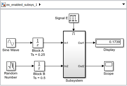
Consider this model, which contains four discrete blocks and a control signal. The discrete blocks are:
Block A, with the sample time of 0.25 seconds
Block B, with the sample time of 0.5 seconds
Signal E is the enable control signal generated by a Pulse Generator with a sample time of 0.125. Its output changes value from 0 to 1 at 0.375 seconds and returns to 0 at 0.875 seconds.
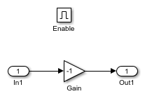
The discrete blocks in the enabled subsystem are:
Block C, within the enabled subsystem, with the sample time of 0.125 seconds
Block D, also within the enabled subsystem, with the sample time of 0.25 seconds

Discrete blocks execute at sample times shown.

Blocks A and B execute independently of the enable control signal because they are not part of the enabled subsystem. When the enable control signal becomes positive, blocks C and D execute at their assigned sample rates until the enable control signal becomes zero again. Block C does not execute at 0.875 seconds when the enable control signal changes to zero.
Goto Blocks
Enabled subsystems can contain Goto blocks. However, only output ports for
blocks with state can connect to Goto blocks. For an example of
using Goto blocks in an enabled subsystem, see the
Locked subsystem in the sldemo_clutch
model.
Alternately Executing Enabled Subsystem Blocks
You can use conditional subsystems with Merge blocks to create sets of subsystems that execute alternately, depending on the current state of the model.
Consider a model that uses two Enabled Subsystem blocks and a Merge block to model a full-wave rectifier, which is a device that converts AC current to pulsating DC current.
Open the example model ex_alternately_executing_model.

Open the subsystem named pos.

This subsystem is enabled when the AC waveform is positive and passes the waveform unchanged to its output.
Open the subsystem named neg.
This subsystem is enabled when the waveform is negative and inverts the waveform.
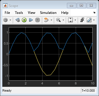
The Merge block passes the output of the currently enabled subsystem along with the original waveform to the Scope block.
Simulate the model. Then, open the Scope block.
Model Examples
For model examples, see:
See Also
Enabled Subsystem | Triggered Subsystem | Enabled and Triggered Subsystem | Function-Call Subsystem