Control Block States and Output of Enabled Subsystem
This example shows how to reset or hold states of blocks inside an Enabled Subsystem block when the subsystem is disabled and how to control the subsystem output. In this example, you see four different combinations of state and output value configurations for both discrete and continuous control signals. When the enabled subsystem is disabled, the combinations work as follows:
Reset state and reset output — Using this configuration, you can reset the states of the blocks inside the subsystem and the output of the subsystem to their initial conditions. When enabled again, the subsystem outputs the initial condition value of its Outport block and other block states use their initial conditions.
Reset state and hold output — Using this configuration, you can reset the states of the blocks inside the subsystem to their initial conditions and hold the output of the subsystem. When enabled again, the subsystem outputs the previous time step value while the other block states use their initial conditions.
Hold state and hold output — Using this configuration, you can hold the states of blocks inside the subsystem at their previous values and the output of the subsystem. When enabled again, the subsystem outputs the previous time step value while the other blocks use the previous state values as their initial conditions.
Hold state and reset output — Using this configuration, you can hold the states of the blocks inside the subsystem at their previous values and reset the output of the subsystem to its initial condition. When enabled again, the subsystem outputs the initial condition value of its Outport block while the other blocks use the previous time step values as their initial conditions.
Open Enabled Subsystem Model
Open the model which contains four enabled subsystems with different configurations for controlling the block states and outputs.

Configure States
Configure the Reset State (Discrete Systems) and Reset State (Continuous Systems) subsystems to reset the integrator states to initial conditions when they are disabled. Double-click each subsystem block, and inside the subsystem, double-click the Enable block. In the Enable Block Parameters dialog box, set States when enabling parameter to reset. For both subsystems, the Initial condition parameter of the integrator is set to 0.
Here, the Reset State (Discrete Systems) subsystem is set to reset when disabled.

Similarly, configure the Held State (Discrete Systems) and Held State (Continuous Systems) subsystems to hold the integrator state values when they are disabled. Double-click each subsystem block, and inside the subsystem, double-click the Enable block. In the Enable Block Parameters dialog box, set States when enabling parameter to held.
Here, the Held State (Discrete Systems) subsystem is set to hold when enabled.

Configure Output
To set the Outport block inside each subsystem to reset, double-click the block. In the Block Parameters dialog box, from the Output when disabled parameter, select reset. Similarly, to hold the values, select held.
Here, the Outport block is set to reset the output value to its Initial output value.

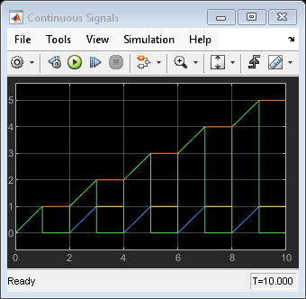
Run Simulation and Visualize Results
Run the simulation and visualize the results. Each Scope block shows one combination of the state and the output of an enabled subsystem when it is disabled.