LC Bandstop Tee
Model LC bandstop tee network
Libraries:
RF Blockset /
Equivalent Baseband /
Ladder Filters
Description
The LC Bandstop Tee block models the LC bandstop tee network described in the block dialog box, in terms of its frequency-dependent S-parameters.
For each inductor and capacitor pair in the network, the block first calculates the ABCD-parameters at each frequency contained in the vector of modeling frequencies. For each series pair, A = 1, B = Z, C = 0, and D = 1, where Z is the impedance of the series pair. For each shunt pair, A = 1, B = 0, C = Y, and D = 1, where Y is the admittance of the shunt pair.
The LC Bandstop Tee block then cascades the ABCD-parameters for each series and shunt
pair at each of the modeling frequencies, and converts the cascaded parameters to
S-parameters using the RF Toolbox™
abcd2s function.
See the Output Port block for information about determining the modeling frequencies.
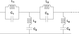
The LC bandstop tee network object is a two-port network as shown in the following circuit diagram.

[L1, L2, L3,
L4, ...] is the value of the 'L' property,
and [C1, C2, C3,
C4, ...] is the value of the 'C'
property.
Examples
Parameters
References
[1] Ludwig, Reinhold and Pavel Bretchko. RF Circuit Design: Theory and Applications. Prentice-Hall, 2000.
[2] Zverev, Anatol I.Handbook of Filter Synthesis . John Wiley & Sons, 1967.
Version History
Introduced in R2013a
See Also
General Passive Network | LC Bandpass Tee | LC Bandstop Pi | LC Highpass Pi | LC Highpass Tee | LC Lowpass Pi | LC Lowpass Tee | Series C | Series L | Series R | Series RLC | Shunt C | Shunt L | Shunt R | Shunt RLC
