Create Plots Using Equivalent Baseband Library Blocks
Available Data for Plotting
RF Blockset™ Equivalent Baseband software lets you validate the behavior of individual RF components and physical subsystems in your model by plotting the following data:
Large- and small-signal S-parameters
Noise figure, noise factor and noise temperature
Output third-order intercept point
Power data
Phase noise
Voltage standing-wave ratio
Transfer function
Group delay
Reflection coefficients
Note
When you plot information about a physical block, the blockset plots the actual frequency response of the block, as specified in the block dialog box. The blockset does not plot the frequency response of the complex-baseband model that it uses to simulate the block, in which the frequency response is centered at zero.
Validate Individual Blocks and Subsystems
You can plot model data for an individual physical block or for a physical subsystem. A subsystem is a collection of one or more physical blocks bracketed by an Input Port block and an Output Port block. To understand the behavior of specific subsystems, plot the data of the corresponding Output Port block after you run a simulation.
To validate the behavior of individual RF components in the model, plot the data of the corresponding physical blocks. You can plot data for individual blocks from each of these components either before or after you run a simulation.
You create a plot by selecting options in the block dialog box, as shown in Create and Modify Subsystem Plots. To learn about the available plots, see Types of Plots. For more information about creating plots, see How to Create a Plot.
Types of Plots
RF Blockset Equivalent Baseband software provides a variety of plots for analyzing the behavior of RF components and subsystems. The following table summarizes the available plots and charts and describes each one.
| Plot Type | Plot Contents |
|---|---|
| X-Y Plane (Rectangular) Plot | Parameters as a function of frequency, input power, or operating condition, such as
|
| Link Budget Plot (3-D) | Parameters as a function of frequency for each component in a physical subsystem where The curve for a given component represents the cumulative contribution of each RF component up to and including the parameter value of that component. For more information, see Link Budget. |
| Polar Plane Plot | Magnitude and phase of parameters as a function of frequency or operating condition, such as
|
| Smith® Chart | Real and imaginary parts of S-parameters as a function of frequency or operating condition, used for analyzing the reflections caused by impedance mismatch. |
| Composite Plot | Multiple plots and charts in one figure. |
To learn how to create these plots, see How to Create a Plot.
Plot Formats
When you create a plot from a block dialog box, you must specify the format of the data for both the x- and y-axes.

These plot options define how RF Blockset Equivalent Baseband software displays the data on the plot.
The available formats vary with the data you select to plot. The data you can plot
depends on the plot type you select. The plot formats determine whether the blockset
converts the data to a new set of units, or performs a calculation on the data. For
example, setting the format to Real tells the blockset to
compute and plot the real part of the parameter.
The following topics describe the available parameters and formats for each plot type:
Composite Data
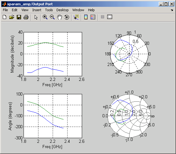
The composite data plot automatically generates four separate plots in one figure window, showing the frequency dependence of several parameters. The following figure shows an example of such a plot.
Example — Composite Data Plot
Note
For composite data plots, you do not need to specify the parameters or the formats—they are set automatically.
The combination of plots differs based on the type of block and the specified block data. The following table describes the contents of the composite data plot for each specification. The Plot Contents column lists the types of plots as they appear on the composite plot, counterclockwise and starting in the upper-left corner. The blockset plots all data as a function of frequency.
| Block | Specified Data | Plot Contents |
|---|---|---|
| General Amplifier or General Mixer | Network parameters OR Network parameters and noise |
|
Network parameters and power OR Network parameters, noise, and power |
| |
| Other Physical block | Network parameters OR Network parameters and noise (S-, Y-, and Z-Parameters Amplifiers and Mixers only) Note Only the General Amplifier and General Mixer blocks accept power data. |
|
X-Y Plane
You can plot any parameters that are relevant to your block on an X-Y plane plot. For this type of plot, you specify data for both the x- and y-axes. If you specify two Y parameters, and you specify different formats for the two Y parameters, the blockset plots the second Y parameter on the right y-axis.
The following table summarizes the available Y parameters and formats. The parameters and formats are the same for both the left and right y-axes.
Note
LS11, LS12, LS21,
and LS22 are large-signal S-parameters. You can plot
these parameters as a function of input power or as a function of
frequency.
Y Parameter | Y Format |
|---|---|
|
|
|
|
|
|
|
|
|
|
|
|
|
|
|
|
|
|
|
|
|
|
|
|
|
|
|
|
|
|
The available X parameters depend on the Y parameters you select. The following table summarizes the available X parameters for each of the Y parameters in the preceding table.
| Y Parameter | X Parameter |
|---|---|
Pout, Phase,
LS11, LS12,
LS21, LS22 | PinFreq |
S11, S12,
S21, S22,
NF, OIP3,
VSWRIn, VSWROut,
GAMMAIn, GAMMAOut,
FMIN, GAMMAOPT,
RN | Freq |
AM/AM, AM/PM | AM |
The following table shows the X formats that are available for the X parameters listed in the preceding table.
| X Parameter | X Format |
|---|---|
Pin | dBmdBWWmW |
Freq | THzGHzMHzKHzHzAuto
(xformat is chosen to provide the best
scaling for the given xparameter
values.) |
AM | Magnitude
(dB)Magnitude
(linear) |
When you import block data from a .p2d or
.s2d file, you can also plot Y parameters as a function
of any operating condition from the file that has numeric values, such as bias.
You can specify an operating condition as the X parameter only when validating
individual blocks, and the format is always None.
This format tells the blockset to plot the operating condition values as they
are specified in the file.
Link Budget
You use the Link budget plot to understand the individual
contribution of each block to a plotted Y parameter value in a physical
subsystem with multiple components between the Input Port and the Output Port
blocks.
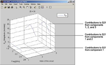
The link budget plot is a three-dimensional plot that shows one or more curves of parameter values as a function of frequency, ordered by the subsystem circuit index.
The following figure shows how the circuit index is assigned to a component in a physical subsystem based on its sequential position in the subsystem.
![]()
A curve on the link budget plot for each circuit index represents the contributions to the parameter value of the RF components up to that index. The following figure shows an example of a link budget plot.
Example — Link Budget Plot
The following table summarizes the Y parameters and formats that are available for a link budget plot.
Y Parameter | Y Format |
|---|---|
|
|
|
|
|
|
|
|
|
|
If you specify two Y parameters, the blockset puts both parameters in a single plot. The Y parameters must have the same formats.
For a link budget plot, the X parameter is always
Freq. The format of the X parameter specifies the
units of the x-axis.
Polar Plane Plots and Smith Charts
You can use RF Blockset Equivalent Baseband software to generate Polar plots and Smith Chart. When you select these plot types, you do not need to specify the format of any Y parameters—the formats are set automatically. If you specify two Y parameters, the blockset puts both parameters in a single plot.
The following table describes the Polar plot and Smith Chart options. It also lists the available Y parameters.
Plot Type | Y Parameter |
|---|---|
|
|
|
|
|
|
|
|
By default, the X parameter is Freq. The format of
the X parameter specifies the units of the x-axis. When you
import block data from a .p2d or .s2d
file, you can also plot Y parameters as a function of any operating condition
from the file that has numeric values, such as bias. You can specify an
operating condition as the X parameter only when validating individual blocks,
and the format is always None.
How to Create a Plot
Double-click the block to open the block dialog box, and select the Visualization tab. The following figure shows the contents of the tab.
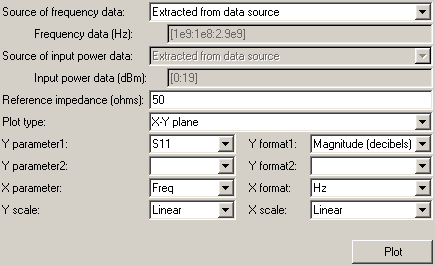
Select the Source of frequency data.

This value is the source of the frequency values at which to plot block data. The following table summarizes the available types of sources for the various types of blocks.
Source of frequency data Description Blocks User-specifiedVector of frequencies that you enter.
When you select
User-specifiedin the Source of frequency data list, the Frequency range (Hz) field is displayed. Enter a vector specifying the range of frequencies you want to plot.For example, to plot block data from 0.3 MHz to 5 GHz by 0.1 MHz, enter
[0.3e6:0.1e6:5e9].Note
When you select PhaseNoise in the Parameter list and
User-specifiedin the Source of frequency data list, the Frequency range (Hz) field is disabled. You use the Phase noise frequency offset (Hz) block parameter to specify the frequency values at which to plot block data.All physical blocks Derived from Input Port parameters(Available after running a simulation or clicking the Update Diagram button )
)Modeling frequencies derived from the Input Port block parameters. For information on how the blockset computes the modeling frequencies, see Determine Modeling Frequencies. All physical blocks Same as the S-parametersFrequency values specified in the Frequency block parameter S-Parameters Passive Network, S-Parameters Amplifier, S-Parameters Mixer Same as the Y-parametersFrequency values specified in the Frequency block parameter. Y-Parameters Passive Network, Y-Parameters Amplifier, Y-Parameters Mixer Same as the Z-parametersFrequency values specified in the Frequency block parameter. Z-Parameters Passive Network, Z-Parameters Amplifier, Z-Parameters Mixer Extracted from data sourceFrequency values imported into the Data file or RFDATA object block parameter. General Passive Network, General Amplifier, and General Mixer Enter the Reference impedance.

This value is the reference impedance to use when plotting small-signal parameters.
Select the Plot type.

This value is the type of plot. For a description of the options, see Types of Plots.
Select the following parameters:
Y Parameter1 — The first parameter for the Y-axis.
Y Parameter2 — The second parameter for the Y-axis (optional).
X Parameter — The parameter for the X-axis.
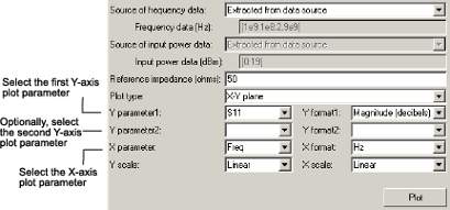
These parameters specify the data to be plotted. The available choices vary with the type of plot. For a description of the options for a particular plot type, see the topic on that plot type in Plot Formats.
If you select a large-signal parameter for one or more y-axis parameters, select the Source of power data.
Note
Large-signal parameters are available only for General Amplifier or General Mixer blocks that contain power data.
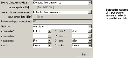
This value is the source of the input power values at which to plot block data. The following table summarizes the available types of sources for the General Amplifier and General Mixer blocks.
Source of frequency data Description Extracted from data sourceInput power values imported into the Data file or RFDATA object block parameter. User-specifiedVector of power values that you enter.
When you select
User-specifiedin the Source of power data list, the Input power data (dBm) field is displayed. Enter a vector specifying the range of power values you want to plot.For example, to plot block data from 1 dBm to 10 dBm by 2 dBm, enter
[1:2:10].Select the following formats:
Y Format1 — The format for the first Y parameter.
Y Format2 — The format for the second Y parameter (optional).
X Format — The format for the X parameter.

These are the X and Y formats for plotting the selected parameter. The available choices vary based on the selected parameter. For a description of the options for a particular plot type, see the topic on that plot type in Plot Formats.
Select the X Scale and Y Scale.
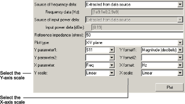
These are the scales on which to plot the data. The available choices are
LinearandLog.Click Plot.
Note
By default, the blockset does not add a legend to some plots. To
display the plot legend, type legend show at the MATLAB® prompt.
For example, see Plot Component Data on Z Smith Chart Using General Amplifier Block.