Group Delay
The group delay of a filter measures of the average time delay of the filter as a function of frequency. For the complex filter frequency response H(ejω), the group delay is defined as the negative first derivative of the phase response for the filter,
where θ represents the phase of the filter and ω represents the frequency in radians per second. For a linear-phase finite impulse response (FIR) filter, the group delay is one-half the order (or span) of the filter. The impulse response length of the filter is (L×N + 1), where N is the filter span in symbols and L is the number of samples per symbol. This sets the delay so that the impulse response before time zero contains a negligible amount of energy and measures the time between the initial and peak response of the filter.
Correlation Between Impulse Peak and Group Delay
The impulse response of the square-root raised cosine (RRC) filter shown in this figure uses an 8 symbol filter span. The peak of the impulse response occurs at the fourth symbol and corresponds with the group delay.
rf = 0.25; % Rolloff factor
span = 8;  % Span of filter
sps = 20;  % Samples per symbol

h1 = rcosdesign(rf,span,sps,"sqrt");
x = [0:length(h1)-1]/sps;
plot(x,h1)

Compute the group delay of the filter by using the grpdelay function. Convert the result to symbols to verify it matches the location of the filter peak.
gd = grpdelay(h1);
groupDelayInSymbols = gd(1)/sps
groupDelayInSymbols =
4
Implications of Delay for Simulations
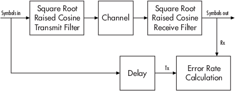
The group delay that results from filtering a signal has implications for other parts of your simulation. For example, suppose you compare the symbol streams marked Symbols In and Symbols Out in this figure by plotting or computing an error rate. Set the delay equal to the total group delay. If your model uses a pair of square root raised cosine filters, sum the combined group delay. To find the total delay between the input and output symbols:
When working in MATLAB®, use the
finddelayfunction.When working in Simulink® use the Find Delay block.
Use one of these methods to make sure you are comparing symbols that truly correspond to each other.
As shown in this figure, you can insert a delay in a path parallel to system component path to align the Symbols In signal with the Symbols Out signal.
When working in MATLAB, use the
alignsignalsfunction.When working in Simulink use the Delay block.
Alternately, when using the
comm.ErrorRateSystem object™ in MATLAB and the Error Rate Calculation block in Simulink, you can adjust the alignment of the input transmitted Symbols In and received Symbols Out with receive delay and computation delay properties and parameters, respectively.
For more information about how to manage delays in a model, see Delay and Latency.