Main Content

OFDM Equalizer

Equalize OFDM modulated signals

Since R2022b

  • OFDM Equalizer block

Libraries:
Communications Toolbox / Equalizers

Description

The OFDM Equalizer block performs frequency-domain equalization to recover OFDM modulated symbols transmitted through a channel.

This icon shows the block with all ports enabled.

OFDM Equalizer block showing optional ports.

Examples

expand all

Apply equalization to an OFDM-modulated QAM signal that has been filtered through a Rayleigh MIMO channel.

The cm_ofdm_equalization model initializes simulation variables and computes path filters in the InitFun callback function. For more information, see Model Callbacks (Simulink).

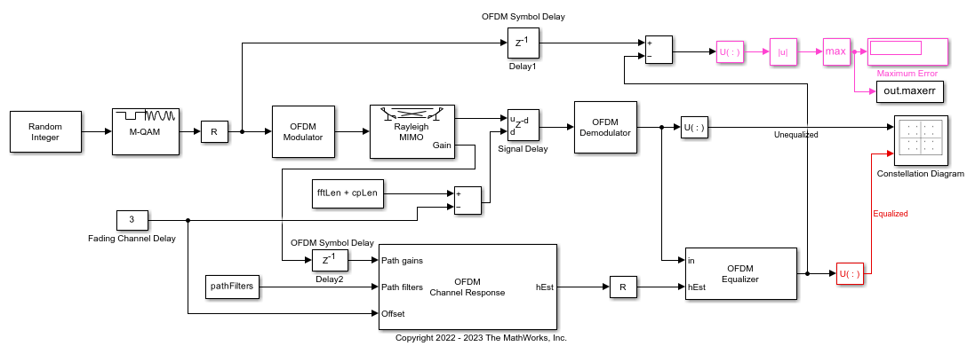
The model generates random integer data, applies 64-QAM, and then applies OFDM to the QAM-modulated signal. The OFDM-modulated signal gets filtered through a MIMO Rayleigh fading channel. The model adds a signal delay in samples, and then OFDM-demodulates the signal. In a parallel path, an OFDM Channel Response block computes the perfect OFDM channel response and an OFDM Equalizer block equalizes the received signal.

The value of the constant block labeled Fading Channel Delay equals the delay of the MIMO Fading Channel block. Since the discrete path delays of the MIMO Fading Channel block are set to [3 9 15]/Fs, the first nonzero value of the channel impulse response has a delay of 3 samples and the Fading Channel Delay value can be any integer in the range [0,3] samples. If the Fading Channel Delay value is greater than 3, intersymbol interference will occur.

The delay block labeled Signal Delay is equal to (fftLen+cpLen) – Fading Channel Delay samples. This removes the MIMO Fading Channel block delay and adds a delay of one OFDM symbol. Each OFDM symbol has (fftLen+cpLen) samples.

The delay blocks labeled Delay1 and Delay2 each add a delay of one OFDM symbol to match the one OFDM symbol delay introduced by the Signal Delay block. Delay1 ensures that the right OFDM Modulator input is used as a reference to calculate the maximum error. Delay2 ensures that the OFDM Demodulator output and the OFDM Channel Response output correspond to the same OFDM symbol.

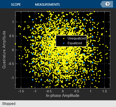
A constellation diagram displays the unequalized and equalized signals. The model computes and displays the maximum error between the transmitted QAM signal and the equalized signal on the receive side.

The maximum computed error is 0.000558.

Ports

Input

expand all

Input signal, specified as a 3-D or 2-D array of received OFDM symbols.

  • If Data format is set to 3-D, the input signal must be specified as an NSC-by-NSymbols-by-NR array. NSC represents the number of OFDM subcarriers, NSymbols represents the number of OFDM symbols, and NR represents the number of receive antennas.

  • If Data format is set to 2-D, the input signal must be specified as an NRE-by-NR array. NRE represents the number of resource elements in an irregular subset of the OFDM subcarrier symbol grid.

Data Types: double | single
Complex Number Support: Yes

Channel estimate, specified as a 3-D array.

  • If Data format is set to 3-D, the block expects hEst to be an NSC-by-NT-by-NR or an (NSC×NSymbols)-by-NT-by-NR array.

    • If hEst is an NSC-by-NT-by-NR array, all OFDM symbols in the input signal in are equalized by the same channel estimate. NSC represents the number of OFDM subcarriers, NT represents the number of transmit antennas, and NR represents the number of receive antennas.

    • If hEst is an (NSC×NSymbols)-by-NT-by-NR array, each OFDM symbol in the input signal in is equalized by the corresponding entry in hEst. NSymbols represents the number of OFDM symbols.

  • If Data format is set to 2-D, the block expects hEst to be an NRE-by-NT-by-NR array. Each OFDM symbol in the input signal in is equalized by the corresponding entry in hEst. NRE represents the number of resource elements in an irregular subset of the OFDM subcarrier symbol grid.

Data Types: double | single
Complex Number Support: Yes

Noise variance estimate for minimum mean squared error (MMSE) equalization, specified as a nonnegative scalar.

Dependencies

The noise variance input port is used only when you set Noise variance source to Input port and Algorithm to Minimum mean squared error.

Data Types: double | single

Output

expand all

Equalized symbols, returned as a 3-D or 2-D array.

  • If Data format is set to 3-D, the block returns an NSC-by-NSymbols-by-NT array. NSC represents the number of OFDM subcarriers, NSymbols represents the number of OFDM symbols, and NT represents the number of transmit antennas.

  • If Data format is set to 2-D, the block returns an NRE-by-NT array. NRE represents the number of resource elements in an irregular subset of the OFDM subcarrier symbol grid.

Soft channel state information, returned as a matrix with size(csi,1) = size(hEst,1) and size(csi,2) = NT = size(hEst,2). NT represents the number of transmit antennas.

Dependencies

To enable this output port, select the Output soft channel state information parameter.

Parameters

expand all

To edit block parameters interactively, use the Property Inspector. From the Simulink® Toolstrip, on the Simulation tab, in the Prepare gallery, select Property Inspector.

Format of the signals, specified as 3-D or 2-D.

When this parameter is set to 3-D, OFDM subcarriers and OFDM symbols use two separate dimensions in the representation of in and out.

  • The in input must be an NSC-by-NSymbols-by-NR array.

  • The out output is returned as an NSC-by-NSymbols-by-NT array.

When this parameter is set to 2-D, OFDM subcarriers and OFDM symbols use one combined dimension in the representation of in and out.

  • The in input must be an NRE-by-NR array.

  • The out output is returned as an NRE-by-NT array.

NSC represents the number of OFDM subcarriers. NSymbols represents the number of symbols. NRE represents the number of resource elements in an irregular subset of the OFDM subcarrier symbol grid. NT represents the number of transmit antennas. NR represents the number of receive antennas.

Equalization algorithm, specified as Minimum mean squared error or Zero-forcing.

  • When this parameter is set to Minimum mean squared error, the block equalizes using the MMSE algorithm.

  • When this parameter is set to Zero-forcing, the block equalizes using the zero-forcing algorithm. When using the zero-forcing algorithm, the noiseVar port value is ignored.

Source of noise variance, specified as one of these values:

  • Input port — Specify this value to use the noiseVar input port to specify the noise variance estimate for MMSE equalization.

  • Property — Specify this value to use the Noise variance parameter to specify the noise variance estimate for MMSE equalization.

Noise variance estimate for MMSE equalization, specified as a nonnegative scalar.

Dependencies

The noise variance setting is used only when you set Noise variance source to Property and Algorithm to Minimum mean squared error.

Select this parameter to enable output port csi containing the soft channel state information.

Type of simulation to run, specified as Interpreted execution or Code generation.

  • Interpreted execution — Simulate the model by using the MATLAB® interpreter. This option requires less startup time, but the speed of subsequent simulations is slower than with the Code generation option. In this mode, you can debug the source code of the block.

  • Code generation — Simulate the model by using generated C code. The first time you run a simulation, Simulink generates C code for the block. The model reuses the C code for subsequent simulations unless the model changes. This option requires additional startup time, but the speed of the subsequent simulations is faster than with the Interpreted execution option.

For more information, see Simulation Modes (Simulink).

Block Characteristics

Data Types

double | single

Multidimensional Signals

yes

Variable-Size Signals

yes

Extended Capabilities

C/C++ Code Generation
Generate C and C++ code using Simulink® Coder™.

Version History

Introduced in R2022b