Design and Analyze Perforated Horn Antenna for RF Applications
This example shows how to design a perforated horn antenna suited for RF applications using custom geometry features of the Antenna Toolbox™ and analyze its scattering parameters. By following this tutorial, you learn how to construct the antenna structure step by step. The antenna structure includes the waveguide, horn taper, side grids, back grids, top and bottom grids. In the end, you learn how to add feed to this structure. This example is particularly useful for engineers and researchers focused on antenna design for high-frequency applications.
Define Geometric Parameters
The perforated horn antenna consists of a rectangular waveguide and a tapered horn with perforations. Define dimensions of the waveguide, tapered horn, and perforation in meters.
% Waveguide
waveguide_length = 10.16e-3;
waveguide_width = 22.86e-3;
waveguide_height = 31e-3;
% Horn Taper
flare_height = 0.01016;
flare_width = 0.02286;
flare_length = 0.053;
% Grid
grid_width = 0.002;
Create Waveguide
Start by creating the waveguide using a box shape. Then modify this shape by removing certain face and applying rotations and translations to achieve the desired orientation.
wShape = shape.Box(Length=waveguide_length,Width=waveguide_width,...
    Height=waveguide_height);
removeFaces(wShape,2);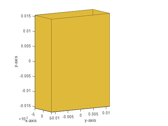
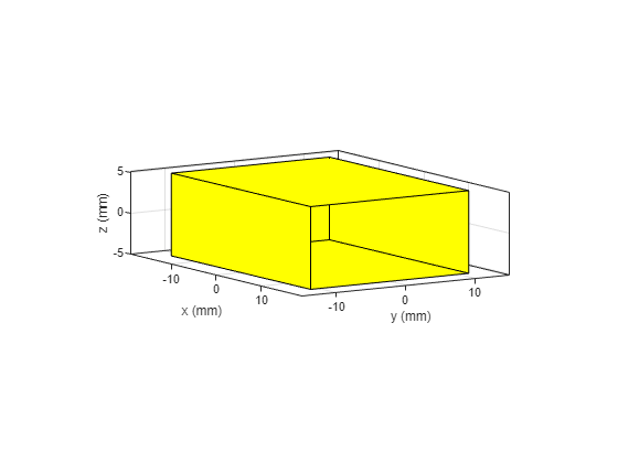
rotate(wShape,90,[0 0 0],[0 1 0]);
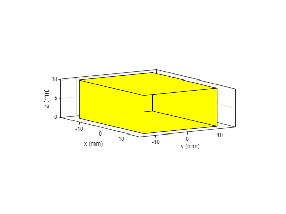
translate(wShape,[0 0 waveguide_length/2]);
Create Tapered Horn Antenna Shape
The tapered horn is crucial for impedance matching and directing the wave propagation. Create the tapered horn antenna shape in three steps as below.
Create Horn
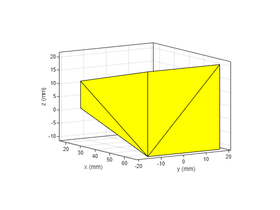
To create a tapered horn, extrude a rectangle, rotate it to align with the waveguide, and then modify its orientation.
rect1 = shape.Rectangle(Length=flare_height,Width=flare_width);
hornTaper1 = extrudeLinear(rect1,flare_length,Scale=[3.149 1.3998],...
    NumSegments=1,Caps=true);
[~] = rotate(hornTaper1,90,[0 0 0],[0 1 0]);
[~] = translate(hornTaper1,[waveguide_height/2 0 flare_height/2]);
removeFaces(hornTaper1,3);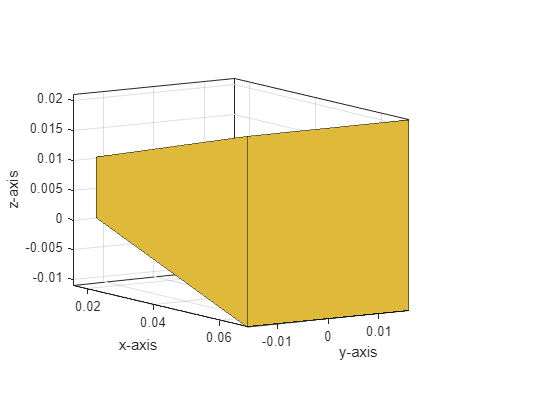
figure
show(hornTaper1)
Add Waveguide
Add waveguide to the tapered horn shape.
wShape = add(wShape,hornTaper1);
Add Perforations
Add perforations in the form of a grid to the tapered horn antenna to fine-tune its radiation pattern and bandwidth. Add various grids by subtracting box shapes from the main structure.
Create Side, Back, Top, and Bottom Grids
This section involves iterative subtraction to create a patterned antenna surface.
Create the side grid.
xs = 0.01200;
ys = 0;
zs = 0.00508;
topbox = shape.Box(Length=grid_width,width=26.86e-3,Height=0.009,Center=[xs ys zs]);
gapbc = 4e-3;

for i=0:6
    topbox.Center = [xs-i*gapbc 0 zs];
    wShape = subtract(wShape,topbox);
end
Repeat similar steps for back, top, and bottom grids with specific dimensions and positions.
% Back grids
xba = -0.0155;
yba = 0.008;
zba = 0.00508;
topbox = shape.Box(Length=0.005,width=grid_width,Height=0.009,Center=[xba yba zba]);
gapbc = 4e-3;
for i=0:4
    topbox.Center = [xba yba-i*gapbc zs];
    wShape = subtract(wShape,topbox);
end
% Top and Bottom grids
xb = 12e-3;
yb = 8e-3;
zb = 11e-3;
gapbc = 3.985e-3;
for i=0:6
    topbox = shape.Box(Length=grid_width,width=0.002,Height=0.025,Center=[xb yb zb]);
    if(i>3)
        topbox.Height = 0.005;
    end
    for j=0:4
        topbox.Center = [xb-i*gapbc yb-j*gapbc zb];
        wShape = subtract(wShape,topbox);
    end
end
Finalize Antenna Structure
After integrating all components, including the waveguide and grids, finalize the antenna structure by adding holes of varying sizes to further refine its performance characteristics.
hornShape = wShape;
xt = 0.018;
yt = 0;
zt = 0.00;
w = 0.002;
Create a box and subtract from the shape to form grids.
topbox = shape.Box(Length=grid_width,width=w,Height=0.050,Center=[xt yt zt]);
gapbc = 3.995e-3;
endp = 11e-3;
endn = -11e-3;
incf = 182.8e-6;
Form holes along the flare length.
for i=0:18
    temp = 1e-3;
    size = 2e-3;
    gapx = 2e-3;
    for k=1:2
        if k==1
            sign = 1;
            st = 1;
        else
            sign = -1;
            st = 0;
        end
        for j=st:6
            if(temp+j*size+j*gapx<=endp)
                w = 0.002;
                yt = sign*j*gapbc;
            elseif(temp+(j-1)*size+j*gapx<endp)
                w = endp - temp - (j-1)*size - j*gapx;
                yt = sign*(j-1)*gapbc + sign*(size/2+gapx+w/2);
            else
                break;
            end
            topbox.Width = w;
            topbox.Center = [xt yt zt];
            hornShape = subtract(hornShape,topbox);
        end
    end
    yt = 0;
    endp = endp + incf;
    xt = xt + 4e-3;
end
figure
show(hornShape)
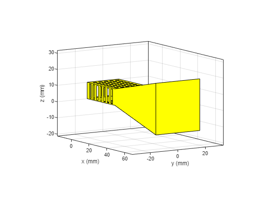
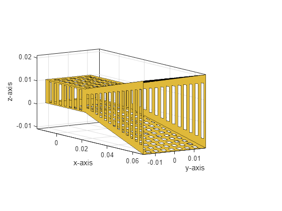
Sequentially subtract box shapes to create holes in the antenna structure. Continue with subsequent holes, adjusting dimensions and positions as required to form holes along flare height.
for i=1:13
    hole1 = shape.Box(Length=0.002,Width=42e-3,Height=0.006+(1.5e-3*(i-1)),Center=[0.018+(4e-3*(i-1)) 0 0.00508]);
    hornShape = subtract(hornShape,hole1);
end

removeFaces(hornShape,5);
Integrate Feed and Analyze Antenna
The final steps involve integrating the feed mechanism and analyzing the antenna's scattering parameters over 8 GHz - 12 GHz frequency range.
Create a rectangular shape for the feed probe.
fo = -7.5e-3;
feedProbe1 = shape.Rectangle(Length=0.00508,Width=0.0014);
feedProbe = copy(feedProbe1);
Create the perforated horn antenna by assigning the custom perforated shape created in previous steps to the Shape property of the customAntenna object.
feedProbe2 = shape.Rectangle(Length=0.0019,Width=0.0038);
[~] = translate(feedProbe2,[-feedProbe1.Length/2 0 0]);
feedProbe1 = feedProbe1 + feedProbe2;
[~] = rotateY(feedProbe1,90);
translate(feedProbe1,[fo 0 feedProbe.Length/2]);
imp_rect = shape.Rectangle(Length=round(feedProbe.Width/sqrt(2),4),Width=round(feedProbe.Width/sqrt(2),4));
[~] = rotateZ(imp_rect,45);
[~] = translate(imp_rect,[fo 0 0]);
hornShape = imprintShape(hornShape,imp_rect);
antShape = add(hornShape,feedProbe1);
ant = customAntenna(Shape=antShape);
Add feed to the perforated horn structure using the createFeed function.
[~] = createFeed(ant,[fo 0 0],1);
figure
show(ant)
title("Perforated Horn Antenna");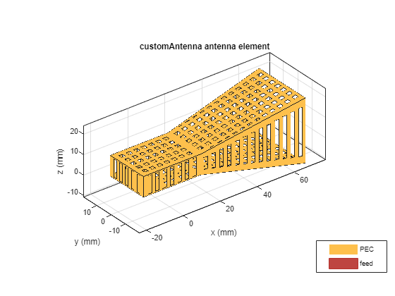
figure
mesh(ant,MaxEdgeLength=0.01,MinEdgeLength=0.002);
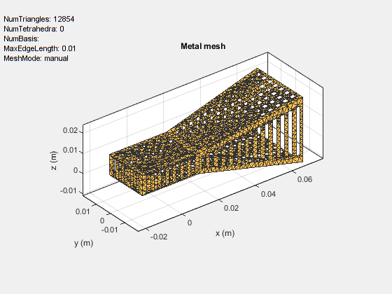
Calculate the S-parameters of this antenna.
s = sparameters(ant,8e9:0.15e9:12e9);
rfplot(s);
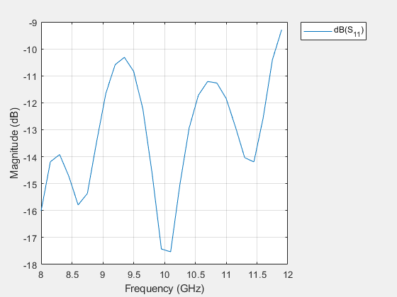
Plot the 3-D radiation pattern of this antenna.
figure
pattern(ant,10e9);
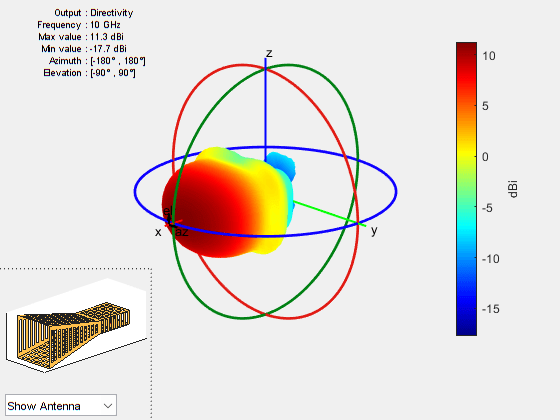
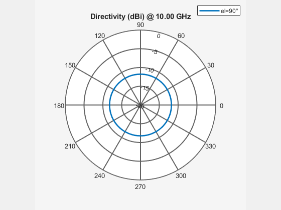
Plot the 2-D azimuth and elevation patterns of this antenna.
figure
patternAzimuth(ant,10e9,90);
figure
patternElevation(ant,10e9);

Conclusion
By meticulously following the steps outlined in this example, you can design a perforated horn antenna tailored for RF applications. The process involves constructing the basic shape, making precise modifications to refine the structure, and analyzing its performance to ensure it meets the desired specifications.
Reference
[1] Huang, Guan-Long, Shi-Gang Zhou, Chow-Yen-Desmond Sim, Tan-Huat Chio, and Tao Yuan. "Lightweight Perforated Waveguide Structure Realized by 3-D Printing for RF Applications."
See Also
Objects
Functions
removeFaces|rotate|translate|extrudeLinear|imprintShape|createFeed|sparameters|pattern