Analysis of Edge-Wall Slotted Waveguide Array Antenna for High-Frequency Applications
This example shows how to analyze the performance of an edge-wall slotted waveguide array antenna. These antennas have many advantages, including high gain, high power handling capacity, and easy manufacturing [1].
Define Waveguide Parameters
Create a waveguide operating at 10.3 GHz as a reference design.
f = 10.3e9;
lamda = 3e8/f;
w = waveguide;
ref = design(w,f);
Define waveguide geometry parameters.
broadWall = round(ref.Width,4); % Width of the waveguide
narrowWall = round(ref.Height,4); % Height of the waveguide
length = 0.3; % Length of the waveguide is adjusted for placing slots
slotSpacing = 0.7*lamda; % Slot spacing
angle = -25; % Random slot angle
initialOffset = 10*slotSpacing; % Initial offset from the feed side end of the waveguide
Create basic shapes, which are the building blocks of the waveguide.
Use shape.Box to create the waveguide body and slot.
wg = shape.Box(Length=length,Width=broadWall,Height=narrowWall);
slot = shape.Box(Length=2e-3,Width=broadWall,Height=narrowWall*2);
Create Edge-Wall Slotted Waveguide Array Antenna
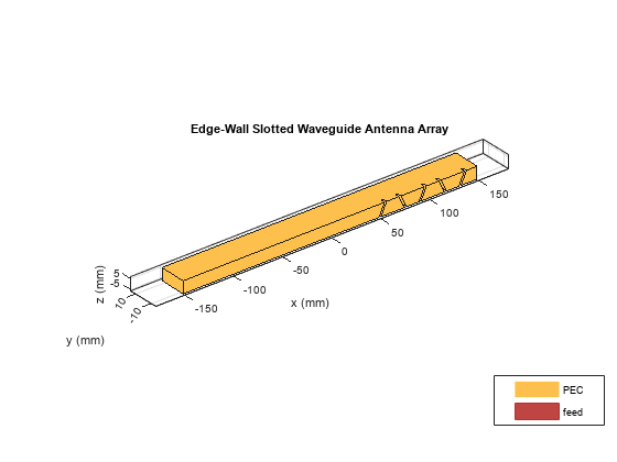
Horizontal slots have maximal radiation, while vertical slots have minimal radiation. The more inclined a slot is towards the horizontal slot, the more abruptly it cuts currents, resulting in higher energy leakage [1]. Run a loop to rotate slots by alternating the sign of the angle for each iteration. Reorient the slots along the waveguide length by a required shift.
for i = 1:5
    tempslot = copy(slot);
    angl = angle*((-1)^i);
    [~] = rotateY(tempslot,angl);
    [~] = translate(tempslot,[-(0.5*length)+initialOffset+((i-1)*slotSpacing) -broadWall+(4e-3) 0]);
    wg = wg - tempslot;
end
Remove the far end face of the box from the feed using the removeFaces function. Calling removeFaces without a second input argument opens an interactive panel, wherein the face that you select can be removed. If you know the face ID, you can remove the face by passing the face ID as the second input argument.
removeFaces(wg,9);

Create Feed Rectangle
Create and align a rectangle that can be assigned as a feed.
feedrect = shape.Rectangle(Length=6.8e-3,Width=5.2e-5);
offset = -(0.5*length) + 4.2e-3;
[~] = translate(feedrect,[offset 0 -narrowWall/2+(feedrect.Length/2)]);
[~] = rotate(feedrect,90,[offset 0 -narrowWall/2+(feedrect.Length/2)],[offset 1 -narrowWall/2+(feedrect.Length/2)]);
Create Antenna from Geometry
Use the customAntenna object to convert the waveguide geometry to an antenna.
ant = customAntenna(Shape=wg);
Manually Mesh Antenna
Manually mesh the antenna with a maximum edge length of 0.95 m.
[~] = mesh(ant,MaxEdgeLength=0.0037966,GrowthRate=0.95);
Assign Feed
Create and assign feed at the desired location on the geometry.
createFeed(ant,[offset 0 -narrowWall/2],1,FeedShape=feedrect);
show(ant)
title("Edge-Wall Slotted Waveguide Antenna Array");
Analyze Edge-Wall Slotted Waveguide Array Antenna
Calculate and plot the reflection coefficient and radiation pattern of the waveguide antenna.
Plot Reflection Coefficient
Plot the reflection coefficient for this antenna over the 9 GHz to 11 GHz frequency band with a reference impedance of 50 ohms.
s = sparameters(ant,linspace(9e9,11e9,60));
rfplot(s)

Plot Radiation Pattern
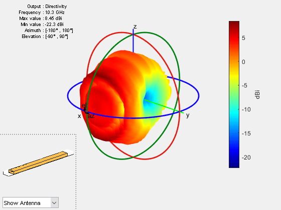
Plot the radiation pattern for this antenna at 10.3 GHz.
pattern(ant,10.3e9);

Conclusion
You build and analyze the basic structure of the edge-wall slotted waveguide array antenna. Instead of alternating the angle of the slot over a loop, you can also pick the angle for each iteration from a predefined list to create custom angled slots across the length.
References
[1] Ke-Ru Chou, Han-Nien Lin, Wei-Hsien Lu, Heng-Wen Chang, and Kwong-Kau Tiong. "Design and Operation of an Edge-Wall Slotted Waveguide Array Antenna with Ultralow Side Lobes for Application of Off-Shore Radar." Journal of Marine Science and Technology 23, no. 5 (1 January 2015). https://doi.org/10.6119/JMST-015-0226-2.
[2] Yusuf, Derry Permana, Fitri Yuli Zulkifli, and Eko Tjipto Rahardjo. "Design of Narrow-wall Slotted Waveguide Antenna with V-shaped Metal Reflector for XBand Radar Application." In 2018 International Symposium on Antennas and Propagation (ISAP), 1–2, 2018.
See Also
Objects
Functions
createFeed|mesh|pattern|sparameters|rfplot
Topics
- Analysis of Broad-Wall Slotted Array Waveguide for High Frequency Applications
- Analysis of Ultrawideband Trident Inset-Fed Monopole Antenna with Conical Ground
- Design And Analyze Spherically Capped Biconical Antenna
- Design and Analyze Perforated Horn Antenna for RF Applications
- Feed Model
- Meshing
- Rotate Antennas and Arrays