Verification Subsystem
Specify proof or test objectives without impacting simulation results or generated code
Libraries:
Simulink Design Verifier /
Verification Utilities
Description
This block is a Subsystem block that is preconfigured to serve as a starting point for creating a subsystem that specifies proof or test objectives for use with the Simulink® Design Verifier™ software.
The Simulink Coder™ software ignores Verification Subsystem blocks during code generation, behaving as if the subsystems do not exist. A Verification Subsystem block allows you to add Simulink Design Verifier components to a model without affecting its generated code.
Note
If a Verification Subsystem block contains blocks that depend on absolute time, and you select an ERT-based target (Simulink Coder) for code generation, set the software environment to absolute time. Open the Configuration Parameters dialog box. In the Code Generation > Interface pane under Software environment, select absolute time. Do not select continuous time. For more information on this setting, see Support: absolute time (Embedded Coder).
When collecting model coverage, the Simulink Coverage™ software only records coverage for Simulink Design Verifier blocks in the Verification Subsystem block; it does not record coverage for any other blocks in the Verification Subsystem.
To create a Verification Subsystem in your model:
Copy the Verification Subsystem block from the Simulink Design Verifier library into your model.
Open the Verification Subsystem block by double-clicking it.
In the Verification Subsystem window, add blocks that specify proof or test objectives. Use Inport blocks to represent input from outside the subsystem.
The Verification Subsystem block in the Simulink Design Verifier library is preconfigured to work with the Simulink Design Verifier software. A Verification Subsystem block must:
Contain no Outport blocks.
Enable its Treat as Atomic Unit parameter.
Specify its Mask type parameter as
VerificationSubsystem.
If you alter the Verification Subsystem block so that the preceding conditions are not met, the Simulink Design Verifier software displays a warning.
Examples
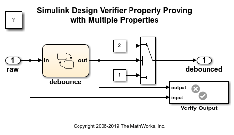
This example shows how to perform a property proving analysis with multiple properties. The model is configured for the analysis to attempt to prove that:
When the current and six previous input values are true, the output will be true.
When the current and six previous input values are false, the output will be false.
open_system('sldvdemo_debounce_validprop');
Extended Capabilities
Version History
Introduced in R2007b