Group Blocks into Subsystems
As a model increases in size and complexity, you can simplify it by grouping blocks into subsystems. A Subsystem block is a block that contains a subset of a model. You can have multiple subsystems in a model, and you can have subsystems inside of other subsystems.
Using subsystems:
Establishes a hierarchy where a Subsystem block is on one layer and the blocks that make up the subsystem are on another. Each subsystem you enter takes you one level deeper in the hierarchy.
Keeps functionally related blocks together.
Helps reduce the number of blocks displayed in your model window.
Establishes an interface with inputs and outputs.
When you make a copy of a subsystem, that copy is independent of the source subsystem. To reuse the contents of a subsystem across a model or across models, consider referenced subsystems, referenced models, or subsystems linked to a block in a custom library. For more information, see Explore Types of Simulink Components.
To create subsystems whose execution depends on other components, use conditionally executed subsystems. For more information, see Explore Types of Subsystems.
Create Subsystems
You can create a subsystem by converting part of an existing model into a subsystem, or by adding a Subsystem block to your model and populating it.
To convert part of a block diagram into a subsystem:
In the Simulink® canvas, drag a selection box over the model elements that you want to include in the subsystem. An ellipsis appears next to the selection box.
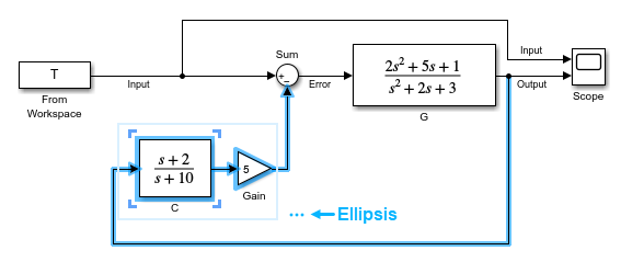
Pause on the ellipsis. An action bar expands.
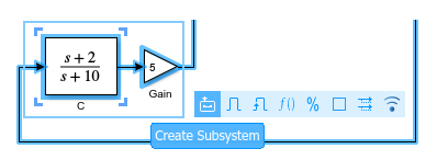
In the action bar, click Create Subsystem or another subsystem option.

When the selection contains blocks that correspond to input and output ports, the new subsystem includes copies of those blocks. The new subsystem does not contain copies of blocks that correspond to control ports.
To create a subsystem from the bottom up:
Decide what type of subsystem you want to create. For information on the types of subsystems, see Explore Types of Subsystems.
Tip
For controllers and other standalone components, define a hard boundary around the related blocks by using a nonvirtual subsystem or referenced model. Defining a hard boundary upfront avoids costly refactoring when you want to generate code for the component.
Open the quick-insert menu by double-clicking the Simulink canvas.
In the search box, start typing the name of the block that corresponds to the type of subsystem you want to implement in your model.
In the list that appears, select the block name. Use the arrow keys and press Enter, or click the block.
To view or edit the contents of a subsystem, double-click the corresponding block. To exit
the subsystem, below the left end of the Simulink Toolbar, click ![]() . For more information on how to navigate the hierarchy of a
model with subsystems, see Navigate Model Hierarchy.
. For more information on how to navigate the hierarchy of a
model with subsystems, see Navigate Model Hierarchy.
The contents of a Subsystem block are saved with the model. If you want to save the contents in a separate file, convert the Subsystem block to a Subsystem Reference block. For more information, see Create and Use Referenced Subsystems in Models. If you save the contents of a subsystem in a separate file, you can add that subsystem to a model by dragging the file into the model canvas. For more information, see Add Components by Dragging Files into Canvas.
Move Blocks Into and Out of Subsystems
Since R2026a
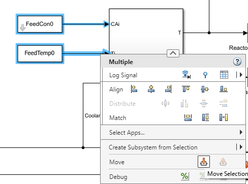
You can move blocks into or out of a subsystem while preserving signal connections and block properties. To move blocks into a subsystem:
Select blocks connected to the subsystem.
Right-click the selected blocks to open the context menu.
From the Move section, select the Move Selection button
 .
.
To move blocks out of a subsystem:
Select blocks within the subsystem that are near the subsystem boundary..
Right-click the selected blocks to open the context menu.
From the Move section, select the Move Selection button
 .
.
Replace Subsystem with Its Contents
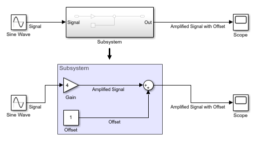
To replace a Subsystem block with its contents, select the Subsystem block. Then, in the Simulink Toolstrip, on the Subsystem Block tab, click Expand.
The contents of the subsystem appear in an area labeled with the name of the replaced block.
For more information, see Expand Subsystem Contents.
Specify Whether Subsystem Is Atomic
When you add a Subsystem block to your model, the block creates a virtual subsystem. Virtual subsystems help visually organize a block diagram. When you group blocks in a virtual subsystem or expand a virtual subsystem, you can affect the execution order of blocks because of the changes to the block paths.
By contrast, an atomic subsystem helps functionally organize a block diagram. When you group blocks in an atomic subsystem or expand an atomic subsystem, you change the model behavior. Each atomic subsystem executes as a single block, or atomic unit, when the parent model executes. The blocks in an atomic subsystem execute consecutively. Atomic subsystems are also known as nonvirtual subsystems.
Note
Conditionally executed subsystems are inherently atomic and nonvirtual. For information on the types of subsystems, see Explore Types of Subsystems.
If you expect a subsystem to grow, make the subsystem atomic so that the subsystem functionally groups the blocks. Specifying that a subsystem is atomic upfront avoids costly refactoring when you want to generate code for the component later. Atomic behavior is necessary for you to convert a subsystem to a model reference.
To make a subsystem atomic, select the Subsystem block in the canvas. Then, in the Simulink Toolstrip, on the Subsystem Block tab, click Make Atomic.
To demonstrate the result of making a subsystem atomic, this block diagram displays the execution order of its blocks, including two Subsystem blocks.

For the Subsystem block named Discrete Cruise Controller,
the block diagram displays an execution order of 4. This subsystem is
nonvirtual and has atomic behavior. The blocks in the subsystem are not part of the
execution order of the current block diagram. Instead, the blocks in the subsystem have
execution orders relative to each other.
For the Subsystem block named Car Dynamics, the block
diagram displays an execution order of {1,5,6,...}. This subsystem is
virtual and does not have atomic behavior. The displayed execution order is for the blocks
in the subsystem, which have execution orders relative to the parent block diagram.

For more information, see Control and Display Execution Order.
Specify Subsystem Read/Write Permissions
You can specify these read/write permissions for a subsystem:
ReadWrite— Enable opening and modification of subsystem contents.ReadOnly— Enable opening but not modification of the subsystem.NotReadorWrite— Disable opening and modification of subsystem.
To control the level of access allowed for the subsystem, set the Read/Write permissions parameter of the Subsystem block.
Note
Restricting read or write access does not prevent the access restrictions from being changed. To hide proprietary information, consider using a protected model. For more information, see Protected Model Capabilities.
When a subsystem is stored in a custom library, you can use the Read/Write permissions parameter on the parent library block to control access for the linked instances of the block. As long as the library link remains intact, the restricted access can prevent people from viewing or modifying the contents of the subsystem while still allowing them to use the subsystem in a model. For more information, see Linked Blocks.
Customize Subsystem
You can change the name of the Subsystem block and modify the block the way that you do with any other block.
For example:
Apply block masks to hide the subsystem content, giving the appearance of an atomic block with its own icon and parameter dialog box. For more information, see Masking Fundamentals.
Use block callbacks to perform actions in response to subsystem modeling actions such as handling an error, deleting a block or line in a subsystem, or closing a subsystem. For more information on block properties, such as callbacks, see Specify Block Properties.