Main Content

Variant Subsystem, Variant Model, Variant Assembly Subsystem

Template subsystem containing Subsystem, Model, or Subsystem Reference blocks as variant choices

  • Variant Subsystem block

Libraries:
Simulink / Ports & Subsystems
HDL Coder / Ports & Subsystems

Description

The Variant Subsystem block enables you to include multiple implementations of a component in a separate hierarchy.

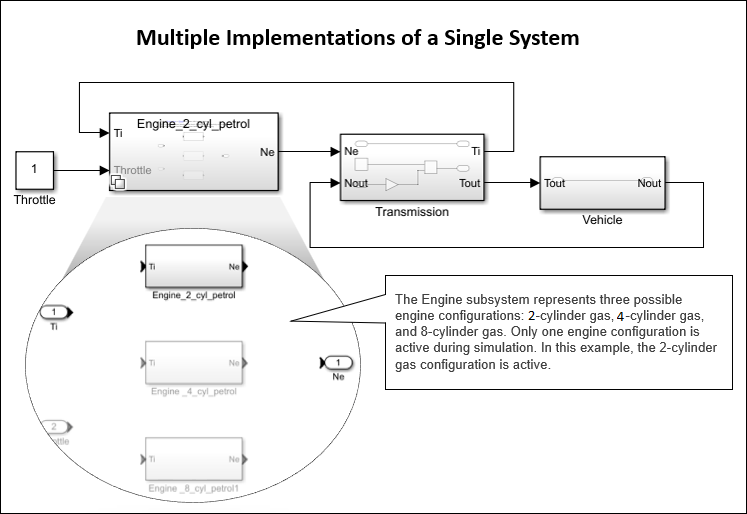
For example, suppose you want to simulate a model that represents a vehicle with three possible engine configurations: 2-cylinder gas, 4-cylinder gas, and 8-cylinder gas. You could implement each engine model as a separate subsystem inside the Variant Subsystem and then switch between the subsystems based on the Types of Variant Control Modes in Variant Blocks you select. For more information, see Introduction to Variant Controls.

Note

Only one implementation of a Variant Subsystem is active during simulation.

Multiple models of an engine inside a Variant Subsystem block

The Variant Subsystem block is a template preconfigured to contain two or more blocks to use as Variant choices. These choices represent multiple implementations of a system. Only one child block is active during model execution. The active child block is referred to as the active variant.

Each variant choice inside the Variant Subsystem block is associated with a Variant control mode and a Variant activation time. The variant control mode determines how to select the active variant. The variant activation time determines a time to activate the choices and to decide whether to include only the active choice or both active and inactive choices in the generated code.

A Variant Subsystem block can contain a mixture of Subsystem blocks, Model blocks, or Create and Use Referenced Subsystems in Models blocks as variant choices. A Variant Subsystem block with only Model blocks as choices is called a Variant Model block. For more information, see Implement Variations in Separate Hierarchy Using Variant Subsystems. A Variant Subsystem block with Model or Create and Use Referenced Subsystems in Models blocks as choices that can added or removed only from external files and not within the block is called a Variant Assembly Subsystem block.

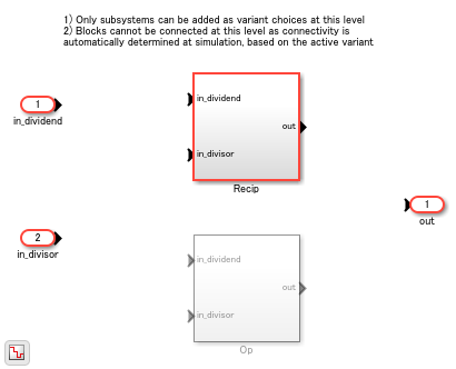
Apart from the variant choices, you can include Inport, control port (Enable, Trigger, Reset, and Function-Call), Outport, or Connection Port (Simscape) blocks inside a Variant Subsystem block. There are no drawn connections between the blocks that are inside the Variant Subsystem blocks. Simulink® automatically wires the active variant to the Inport and Outport blocks of the Variant Subsystem during model compilation. The blocks representing variant choices can have input and output ports that differ in number from the input and output ports in the parent Variant Subsystem block. For more information, see Map Inports and Outports of Variant Choices in Variant Subsystem.

Using Variant Subsystem block allows you to:

  • Mix Subsystem, Model, and Subsystem Reference blocks as variant choices.

  • Model components that do not have similar interface. You can have different numbers of inports and outports for multiple variant choices inside a Variant Subsystem. However, the conditions listed in Map Inports and Outports of Variant Choices in Variant Subsystem must be met.

  • Establish a hierarchical block diagram, where the Variant Subsystem block is on one layer and the variant choices are on another layer.

  • Keeps functionally related blocks together.

  • Reduce the complexity of your model.

  • During model compilation, Simulink eliminates inactive blocks throughout the model, depending on the variant activation time you select.

The color and icon of the variant badge on the block icon changes depending on the values of the Variant activation time, Variant control mode, and Propagate conditions outside of variant subsystem parameters set on the block. For more information, see Variant Badges.

Variant Assembly Subsystem

A Variant Assembly Subsystem block enables you to add or remove its variant choices from external sources without modifying the model. A Variant Assembly Subsystem block can contain Model blocks, Subsystem Reference blocks, or both as its variant choices. You specify the source of variant choices in the block parameter dialog box once and then modify the source to add or remove the variant choices from the block. Unlike Variant Subsystem, you cannot manage the variant choices from inside the Variant Assembly Subsystem block. For more information, see Add or Remove Variant Choices of Variant Assembly Subsystem Blocks Using External Files.

When you load a model with a Variant Assembly Subsystem block that has variant choices stored in subsystem files, by default only the active choice is loaded to optimize the loading time for models. However, if you initialize a model programmatically using find_system, get_param, or set_param some inactive choices may also get loaded. You can move or resize the Model or Subsystem Reference blocks inside the Variant Assembly Subsystem.

Note

To convert a Variant Subsystem block to a Variant Assembly Subsystem block, follow the steps in Convert Variant Subsystem to Variant Assembly Subsystem.

Ports

During simulation, Simulink disables the inactive ports in a Variant Subsystem block.

Input

expand all

Each Subsystem, Model, or Subsystem Reference block contained within a Variant Subsystem represents one variant choice. The variant choices can contain Inport, control port (Enable, Trigger, Reset, and Function-Call), or Connection Port (Simscape) blocks at its input. The variant choices can have input ports that differ in number from the input ports in the parent Variant Subsystem block. However, the conditions described in Map Inports and Outports of Variant Choices in Variant Subsystem must be met.

Output

expand all

Each Subsystem, Model, or Subsystem Reference block contained within a Variant Subsystem represents one variant choice. The variant choices can contain Outport or Connection Port (Simscape) blocks at its output. The variant choices can have output ports that differ in number from the output ports in the parent Variant Subsystem block. However, the conditions described in Map Inports and Outports of Variant Choices in Variant Subsystem must be met.

Note

The unconnected outports (inactive outports) of a Variant Subsystem outputs a ground value. To output a value other than ground, select the Specify output when source is unconnected parameter of the Outport block and specify a value.

Map Inports and Outports of Variant Choices in Variant Subsystem

A Variant Subsystem block allows you to use a combination of Subsystem, Model, or Subsystem Reference blocks as variant choices. The inputs that the Variant Subsystem block receives from upstream model components map to the input and output ports of the variant choices.

The blocks that represent variant choices can have input and output ports that differ in number from the input and output ports in the parent Variant Subsystem block. However, the following conditions must be met:

  • The variant choices must have same set of inports as the Variant Subsystem container block or it must be a subset of ports on the container block.

  • The variant choices must have same set of outports as the Variant Subsystem container block or it must be a subset of ports on the container block.

  • If the Variant Subsystem container block has control ports:

    • The type of control port blocks in all the variant choices must be same as the Variant Subsystem block. For example, you cannot use Enabled Subsystem and Function-Call Subsystem blocks as choices within a Variant Subsystem block.

    • The control port on the Variant Subsystem block and the corresponding control ports on its variant choices must have the same name. For example, if the name of the control port on the Variant Subsystem is fcn, then the name of the corresponding control ports on all its variant choices must also be fcn.

Parameters

expand all

To access these parameters, right-click the variant badge on the block icon and select Block Parameters. For more information, see Variant Badges.

The variant control that determines the active variant choice can be any of these types.

  • expression — In expression mode, Simulink chooses the active variant based on the evaluation of the variant conditions. When a condition expression evaluates to true, the corresponding variant choice becomes active. When a condition expression evaluates to false, the corresponding variant choice becomes inactive. See Switch Between Choices Using Condition Expressions in Variant Blocks.

  • label — In label mode, Simulink chooses the active variant based on the name of the variant. The variant control is a string and does not require you to create any variable in any workspaces. See Switch Between Choices Using Labels in Variant Blocks.

  • sim codegen switching — To automatically switch between the variants for simulation and code generation workflows without creating any workspace variable, use sim codegen switching mode. When you simulate a model, Simulink automatically chooses the sim branch as the active choice. Similarly, when you do a software-in-the-loop (SIL) or processor-In-Loop (PIL) simulation, generate code, or use external mode, Simulink automatically chooses the codegen branch. See Switch Between Choices for Simulation and Code Generation Workflows Without Using Control Variables in Variant Blocks.

For more information on variant control modes, see Introduction to Variant Controls. For a comparison between different types of variant control modes, see Compare Different Types of Variant Control Modes in Variant Blocks.

Dependencies

The availability of different variant activation times depends on the type of the Variant control mode that you specify. The Variant activation time parameter determines the time when Simulink sets the active choice. The parameter also determines which variability to include in the generated code. This table explains the variant activation time supported by each variant control mode.

Variant activation time
Variant control modeupdate diagramupdate diagram analyze all choicescode compilestartup
expression
labelxxx
sim codegen switchingxx

Programmatic Use

Block Parameter: VariantControlMode
Type: character vector
Values: expression | label | sim codegen switching |
Default: expression

This parameter determines which variability to include in the simulation and code generation workflows. For more information, see Activate Variant During Different Stages of Simulation and Code Generation Workflow.

You can set the Variant activation time parameter as:

  • update diagram — When you execute the model, only the active choice is included in the simulation and the code generation workflow. Generated code contains only the active choice.

  • update diagram analyze all choices — When you execute the model, both active and inactive choices are analyzed for consistency across the model. However, only the active choice is included in the simulation and the code generation workflow. Generated code contains only the active choice.

  • code compile — When you execute the model, both active and inactive choices are analyzed for consistency across the model, and all choices are included in the simulation and the code generation workflow. Generated code contains both the active and inactive choices enclosed in the preprocessor conditionals #if and #elif. However, the executable built from the generated code contains only active choice.

  • startup — When you execute the model, both active and inactive choices are analyzed for consistency across the model, and all choices are included in the simulation and the code generation workflow. With this option, you can improve the speed of iterative simulations using fast restart. For more information, see Run Iterative Simulations Without Recompiling Model for Variant Systems Using Fast Restart. Code generated from the model contains both the active and inactive choices that are enclosed in regular if conditions. The executable built from the generated code also contains both active and inactive choices.

  • inherit from Simulink.VariantControl — When you execute the model, the block inherits the activation time from its variant control variables of type Simulink.VariantControl. If a variant block has multiple variant control variables of type Simulink.VariantControl, then all those variables must have the same activation time.

Dependencies

The availability of different variant activation times depends on the type of the variant control mode that you specify. The Variant activation time parameter determines when Simulink sets the active choice. The parameter also determines which variability to include in the generated code. This table explains the variant activation time supported by each variant control mode.

Variant activation time
Variant control mode update diagramupdate diagram analyze all choicescode compilestartup
expression
labelxxx
sim codegen switchingxx

Programmatic Use

Block Parameter: VariantActivationTime
Type: character vector
Values: update diagram | update diagram analyze all choices | code compile | startup
Default: update diagram

When you specify a variable of type listed in Types of Variant Control Variables (Operands) in Variant Blocks, Simulink generates variant control expressions for the variant choices of the Variant Assembly Subsystem block. The Variant control variable that you specify here is on the left side and the members of the Variant enumeration choice are on the right side of the generated expressions. Both the sides are related by ==.

The variant control variable acts as a switch to change the active variant choice. You specify a value for a variant control variable and run the simulation. During simulation, Simulink evaluates the variant control expressions to determine the active variant choice. When an expression evaluates to true, the corresponding variant choice is set active. To change the active variant, change the value of the variant control variable such that the corresponding variant control expression evaluates to true turns active.

Dependencies

This parameter is available only in Variant Assembly Subsystem block. To enable this parameter, set Variant control mode to expression.

Programmatic Use

Block Parameter: VariantControlVariable
Type: character vector
Values: Simulink.VariantControl, scalar variable, Simulink.Parameter, struct
Default: ''

To add Model or Subsystem Reference blocks as variant choices to a Variant Assembly Subsystem block, specify an enumeration class name that contains the corresponding model or subsystem filenames as its members. You can then validate the enumeration class using the Refresh button in the Variant choices table. On a successful validation, the members of the enumeration class are added as variant choices to the Variant Assembly Subsystem block. Each choice has a variant control expression with Variant control variable on its left side and the members of the Variant choices enumeration that you specify here on its right side. Both the sides of the expression are related by ==. The newly added variant choices and their corresponding control expressions are displayed in the Variant choices table.

To remove variant choices from a Variant Assembly Subsystem block, remove the corresponding members from the enumeration class that you specify here. You cannot manage the variant choices from inside the Variant Assembly Subsystem block.

The enumeration class that you specify must be on the search path of your current MATLAB® session. For information on how to add files or folders to the search path, see addpath.

For more information on how to add choices using the Variant choices enumeration parameter, see Add or Remove Variant Choices of Variant Assembly Subsystem Blocks Using External Files.

Dependencies

This parameter is available only in Variant Assembly Subsystem block. To enable this parameter, set Variant control mode to expression.

Programmatic Use

Block Parameter: VariantChoicesEnumeration
Type: character vector
Values: enumeration class defined using classdef or Simulink.defineIntEnumType
Default: ''

To add Model or Subsystem Reference blocks as variant choices to a Variant Assembly Subsystem block, specify the corresponding model or subsystem file names. The file names must be specified as a MATLAB expression that returns a one-dimensional cell array of character vectors when evaluated or an array of strings. You can then validate the expression using the Refresh button in the Variant choices table. On a successful validation, the blocks that correspond to the specified files are added as variant choices to the Variant Assembly Subsystem block. For each choice, a variant control label is generated. The name of the variant control label is same as the name of the choice. The newly added variant choices and their corresponding control labels are displayed in the Variant choices table.

To remove variant choices from a Variant Assembly Subsystem block, modify the expression specified in this parameter. You cannot manage the variant choices of a Variant Assembly Subsystem block from inside the block.

The MATLAB expression that you specify must contain either of these:

  • Model or subsystem file names that are on the search path of your current MATLAB session. For example, if you specify {'model1.slx', 'subsystemRef1.slx'} as a specifier, the blocks that correspond to the model1.slx and subsystemRef1.slx files are added as variant choices of the Variant Assembly Subsystem block.

  • File name patterns that match the model or subsystem file names on the MATLAB path. The paths in the pattern can be absolute or relative to the parent folder of the model that contains the Variant Assembly Subsystem block. For example, if you specify {'folder_1/*.slx', 'folder_2/*.slx'} as a specifier, Simulink passes the character vectors folder_1/* and folder2/* to the dir function. The function then returns the model and the subsystem files that are located inside the folder1 and folder2 folders. The blocks that correspond to the returned files are added as variant choices of the Variant Assembly Subsystem block.

For information on how to add files or folders to the search path, see addpath.

For more information on how to specify choices in the Variant choices specifier parameter, see Add or Remove Variant Choices of Variant Assembly Subsystem Blocks Using External Files.

Dependencies

This parameter is available only in Variant Assembly Subsystem block. To enable this parameter, set Variant control mode to label.

Programmatic Use

Parameter: VariantChoicesSpecifier
Type: character vector
Value: Any MATLAB expression that evaluate to a one-dimensional cell array of file names or file name patterns.
Default: ''

The table has a row for each variant choice contained in the Variant Subsystem. If there are no variant choices, the table is empty.

You can use buttons to the left of the Variant choices table to modify the elements in the table.

To...Click...
Create and add a new subsystem choice: Create a new Subsystem block as a variant choice and add an entry for the new choice in the table.the Create and add a new subsystem choice button
Create and add a new model variant choice: Create a new Model block as a variant choice and add an entry for the new choice in the table.the Create and add a new model variant choice button
Delete selected variant choices: Delete variant choices permanently.

the Delete selected variant choices button

Create/Edit selected variant object: Create or edit a Simulink.VariantExpression object in the global workspace and specify the variant condition using the Simulink.VariantExpression object parameter dialog box.

Note

For a model that uses the base workspace, this operation creates the Simulink.VariantExpression object in the base workspace and the object is available only for the current MATLAB session. To permanently store the data, save the object in a MAT file or MATLAB script.

the Create or Edit selected variant object button
Open selected variant choice block: Open the Subsystem block for the selected row.the Open selected variant choice block button
Refresh dialog information from Variant Subsystem contents: Update the Variant choices table according to the variant choices and values of the variant control in the global workspace.the Refresh dialog information from Variant Subsystem contents button

Dependencies

The Variant Assembly Subsystem block allows you to only open the selected variant choice and refresh the list of variant choices using the buttons in this section. To add new variant choices to the Variant Assembly Subsystem block, see Add or Remove Variant Choices of Variant Assembly Subsystem Blocks Using External Files.

This parameter is read-only.

This parameter displays the name of the choices. Each choice has a variant control in the form of labels, expressions, or switches. For Variant Assembly Subsystem in the label mode, no separate variant control is available. The name of the choice is used as a variant control to set the active choice.

A name for a choice, specified as a string.

Dependencies

To enable this parameter, set Variant control mode to label.

Specify the condition expression to determine the active choice. When a condition expression evaluates to true, Simulink activates the corresponding variant choice. When a condition expression evaluates to false, Simulink deactivates the corresponding variant choice.

The variant controls can be:

Here, A and B are operands called as variant control variables. ==, ~=, and && are operators in the condition expression. The condition expression can contain one or more such variant control variables and operators. For information on supported types and storage location of variant control variables, see Types of Variant Control Variables (Operands) in Variant Blocks and Storage Locations for Variant Control Variables (Operands) in Variant Blocks. For information on operators, see Types of Operators in Variant Blocks for Different Activation Times.

For more information, see Switch Between Choices Using Condition Expressions in Variant Blocks.

Note

In Variant Assembly Subsystem block, this parameter is a list of auto-generated boolean expressions with Variant control variable on the left-hand side and the members of the Variant enumeration choice are on the right-hand side of the expressions. Both the sides of the expressions are connected with ==. This parameter is read-only.

Programmatic Use

Structure field: Represented by the read-only variant.Name field in the Variant parameter structure
Type: character vector
Value: variant control that is associated with the variant choice
Default: 'variant'

This parameter is read-only.

This parameter displays the condition expression specified as Simulink.VariantExpression object. To change or edit the condition expression, use the Simulink.VariantExpression parameter dialog box that appears when you double-click the object in the workspace.

Note

The operands that you specify in a condition expression of type Simulink.VariantExpression must be defined in the base workspace or a data dictionary. Specifying operands that are defined in the mask or model workspace is not supported.

This list contains the labels of all the variant choices. To set an active choice, select a label from the list. The corresponding choice becomes active. Alternatively, you can follow the approaches described in Set Active Choices Using Variant Control Labels to change the active choice in label mode.

Dependencies

To enable this parameter, set the Variant control mode parameter to label.

Programmatic Use

Parameter: LabelModeActivechoice
Type: character vector
Value: if no label mode active choice is specified, the value is empty. If label mode active choice is specified, the value is the name of the label mode active choice.
Default: ''
  • off — Simulink generates an error when there is no active variant choice.

  • on — When you select this option and if there is no active variant choice, Simulink simulates the model without any active variant choice in the Variant Subsystem. Simulink disconnects all the blocks connected to the input and output stream of Variant Subsystem block, thus removing the variant regions completely from the model. The inactive outports of the Subsystem output a ground value. To output a value other than ground, select the Specify output when source is unconnected parameter of the Outport block and specify a value of your choice.

Dependencies

This parameter is available only if there are no default variant choices in the Variant Subsystem and if you set Variant control mode to expression.

Programmatic Use

Parameter: AllowZeroVariantControls
Type: character vector
Value: 'off' | 'on'
Default: 'off'

When you select the Propagate conditions outside of variant subsystem parameter, Simulink propagates the variant condition of the underlying blocks to the Variant Subsystem container block so the subsystem can adapt its interface to the state of the underlying blocks. Ports that are mapped to the ports on the active choice becomes active. Ports that are not mapped to the ports on the inactive choice becomes inactive. Selecting this option ensures that the components outside of the Variant Subsystem are aware of the active and inactive state of blocks within the Variant Subsystem block. For more information, see Propagate Variant Conditions to Define Variant Regions Outside Variant Subsystems and Propagate Variant Conditions to Control Execution of Conditional Subsystems

Note

Variant conditions do not propagate outside a Variant Subsystem block if all variant choices within the block have the same interface.

Programmatic Use

Parameter: PropagateVariantConditions
Type: character vector
Value: 'off' | 'on'
Default: 'off'

  • on — Simulate with variant choices that have input and output ports that differ in number from the input and output ports of the Variant Subsystem block.

  • off — When you simulate with this option, if there is inconsistency in the interface, Simulink will generate errors with fix-it actions to match the ports of the variant choices to the Variant Subsystem block.

Programmatic Use

Parameter: AllowFlexibleInterface
Type: character vector
Value: 'off' | 'on'
Default: 'on'

Block Characteristics

Data Types

Booleana | busa | doublea | enumerateda | fixed pointa | halfa | integera | singlea | stringa

Direct Feedthrough

no

Multidimensional Signals

yesa

Variable-Size Signals

yesa

Zero-Crossing Detection

no

a Actual data type or capability support depends on block implementation.

Extended Capabilities

Version History

Introduced in R2010b

expand all