PID Controller (2DOF)
Continuous-time or discrete-time two-degree-of-freedom PID controller
Libraries:
Simulink /
Continuous
Description
The PID Controller (2DOF) block implements a two-degree-of-freedom PID
controller (PID, PI, or PD). The block is identical to the Discrete PID
Controller (2DOF) block with the Time domain parameter
set to Continuous-time.
The block generates an output signal based on the difference between a reference signal and a measured system output. The block computes a weighted difference signal for the proportional and derivative actions according to the setpoint weights (b and c) that you specify. The block output is the sum of the proportional, integral, and derivative actions on the respective difference signals, where each action is weighted according to the gain parameters P, I, and D. A first-order pole filters the derivative action.
The block supports several controller types and structures. Configurable options in the block include:
Controller type (PID, PI, or PD) — See the Controller parameter.
Controller form (Parallel or Ideal) — See the Form parameter.
Time domain (continuous or discrete) — See the Time domain parameter.
Initial conditions and reset trigger — See the Source and External reset parameters.
Output saturation limits and built-in anti-windup mechanism — See the Limit output parameter.
Signal tracking for bumpless control transfer and multiloop control — See the Enable tracking mode parameter.
As you change these options, the internal structure of the block changes by activating different variant subsystems. (See Implement Variations in Separate Hierarchy Using Variant Subsystems.) To examine the internal structure of the block and its variant subsystems, right-click the block and select Edit Mask > Look Inside Mask.
Control Configuration
In one common implementation, the PID Controller block operates in the feedforward path of a feedback loop.
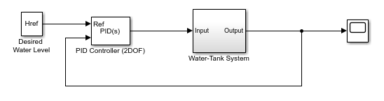
For a single-input block that accepts an error signal (a difference between a setpoint and a system output), see PID Controller.
PID Gain Tuning
The PID controller coefficients and the setpoint weights are tunable either manually or automatically. Automatic tuning requires Simulink® Control Design™ software. For more information about automatic tuning, see the Select tuning method parameter.
Examples
Two Degree-of-Freedom PID Control for Setpoint Tracking
Regulate the speed of an electric motor using two degree-of-freedom PID control with set-point weighting. This model uses the PID Controller (2DOF) block. The model changes the setpoint values between 60 and 30 rpm. To convert the units to rad/s for use in the PID controller, the model uses a Signal Conversion block.
Ports
Input
Reference signal for plant to follow, as shown.
When the reference signal is a vector, the block acts separately on each signal, vectorizing the PID coefficients and producing a vector output signal of the same dimensions. You can specify the PID coefficients and some other parameters as vectors of the same dimensions as the input signal. Doing so is equivalent to specifying a separate PID controller for each entry in the input signal.
Data Types: single | double | int8 | int16 | int32 | int64 | uint8 | uint16 | uint32 | uint64 | fixed point
Feedback signal for the controller, from the plant output.
Data Types: single | double | int8 | int16 | int32 | int64 | uint8 | uint16 | uint32 | uint64 | fixed point
Since R2024a
Supply the derivative of the plant signal y directly as an input to the block. This is helpful when you have the derivative signal available in your model and want to skip the computation of the derivative inside the block.
Dependencies
To enable this input port, select a controller type that has derivative action and enable Use externally sourced derivative.
Data Types: single | double | int8 | int16 | int32 | int64 | uint8 | uint16 | uint32 | uint64 | fixed point
Proportional gain, provided from a source external to the block. External gain input is useful, for example, when you want to map a different PID parameterization to the PID gains of the block. You can also use external gain input to implement gain-scheduled PID control. In gain-scheduled control, you determine the PID coefficients by logic or other calculation in your model and feed them to the block.
Dependencies
To enable this port, set Controller parameters Source to external.
Data Types: single | double | int8 | int16 | int32 | int64 | uint8 | uint16 | uint32 | uint64 | fixed point
Integral gain, provided from a source external to the block. External gain input is useful, for example, when you want to map a different PID parameterization to the PID gains of the block. You can also use external gain input to implement gain-scheduled PID control. In gain-scheduled control, you determine the PID coefficients by logic or other calculation in your model and feed them to the block.
When you supply gains externally, time variations in the integral gain are also integrated. This result occurs because of the way the PID gains are implemented within the block. For details, see the Controller parameters Source parameter.
Dependencies
To enable this port, set Controller parameters Source to
external, and set Controller to
a controller type that has integral action.
Data Types: single | double | int8 | int16 | int32 | int64 | uint8 | uint16 | uint32 | uint64 | fixed point
For discrete-time controllers, integral gain multiplied by the controller sample time, provided from a source external to the block. External gain input is useful, for example, when you want to map a different PID parameterization to the PID gains of the block. You can also use external gain input to implement gain-scheduled PID control. In gain-scheduled control, you determine the PID coefficients by logic or other calculations in your model and feed them to the block.
Note
PID tuning tools, such as the PID Tuner app and Closed-Loop PID Autotuner block, tune the gain I but not I*Ts. Therefore, multiply the integral gain value you obtain from a tuning tool by the sample time before you supply it to this port.
When you use I*Ts instead of I, the block requires fewer calculations to perform integration. This improves the execution time of the generated code.
For continuous-time controllers, disable Use I*Ts and use the I port instead.
Dependencies
To enable this port, set Controller parameters Source to external, set Controller to a controller type that has integral action, and enable the Use I*Ts parameter.
Data Types: single | double | int8 | int16 | int32 | int64 | uint8 | uint16 | uint32 | uint64 | fixed point
Derivative gain, provided from a source external to the block. External gain input is useful, for example, when you want to map a different PID parameterization to the PID gains of the block. You can also use external gain input to implement gain-scheduled PID control. In gain-scheduled control, you determine the PID coefficients by logic or other calculation in your model and feed them to the block.
When you supply gains externally, time variations in the derivative gain are also differentiated. This result occurs because of the way the PID gains are implemented within the block. For details, see the Controller parameters Source parameter.
Dependencies
To enable this port, set Controller parameters Source to
external, and set Controller to
a controller type that has derivative action.
Data Types: single | double | int8 | int16 | int32 | int64 | uint8 | uint16 | uint32 | uint64 | fixed point
Derivative filter coefficient, provided from a source external to the block. External coefficient input is useful, for example, when you want to map a different PID parameterization to the PID gains of the block. You can also use the external input to implement gain-scheduled PID control. In gain-scheduled control, you determine the PID coefficients by logic or other calculation in your model and feed them to the block.
Dependencies
To enable this port, set Controller parameters Source to
external, and set Controller to a
controller type that has a filtered derivative.
Data Types: single | double | int8 | int16 | int32 | int64 | uint8 | uint16 | uint32 | uint64 | fixed point
Proportional setpoint weight, provided from a source external to the block. External input is useful, for example, when you want to map a different PID parameterization to the PID gains of the block. You can also use the external input to implement gain-scheduled PID control. In gain-scheduled control, you determine the PID coefficients by logic or other calculation in your model and feed them to the block.
Dependencies
To enable this port, set Controller parameters Source to
external.
Data Types: single | double | int8 | int16 | int32 | int64 | uint8 | uint16 | uint32 | uint64 | fixed point
Derivative setpoint weight, provided from a source external to the block. External input is useful, for example, when you want to map a different PID parameterization to the PID gains of the block. You can also use the external input to implement gain-scheduled PID control. In gain-scheduled control, you determine the PID coefficients by logic or other calculation in your model and feed them to the block.
Dependencies
To enable this port, set Controller parameters Source to
external, and set Controller to
a controller type that has derivative action.
Data Types: single | double | int8 | int16 | int32 | int64 | uint8 | uint16 | uint32 | uint64 | fixed point
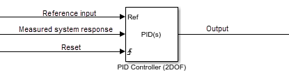
Trigger to reset the integrator and filter to their initial conditions. Use the
External reset parameter to specify what kind of signal
triggers a reset. The port icon indicates the trigger type specified in that parameter.
For example, the following illustration shows a continuous-time PID Controller (2DOF)
block with External reset set to
rising.
When the trigger occurs, the block resets the integrator and filter to the initial conditions specified by the Integrator Initial condition and Filter Initial condition parameters or the I0 and D0 ports.
Note
To be compliant with the Motor Industry Software Reliability Association (MISRA™) software standard, your model must use Boolean signals to drive the external reset ports of the PID controller block.
Dependencies
To enable this port, set External reset to any value other than none.
Data Types: single | double | int8 | int16 | int32 | int64 | uint8 | uint16 | uint32 | uint64 | fixed point | Boolean
Integrator initial condition, provided from a source external to the block.
Dependencies
To enable this port, set Initial conditions Source to
external, and set Controller to
a controller type that has integral action.
Data Types: single | double | int8 | int16 | int32 | int64 | uint8 | uint16 | uint32 | uint64 | fixed point
Initial condition of the derivative filter, provided from a source external to the block.
Dependencies
To enable this port, set Initial conditions Source to
external, and set Controller to a
controller type that has derivative action.
Data Types: single | double | int8 | int16 | int32 | int64 | uint8 | uint16 | uint32 | uint64 | fixed point
Upper limit of the block output, provided from a source external to the block. If the weighted sum of the proportional, integral, and derivative actions exceeds the value provided at this port, the block output is held at that value.
Dependencies
To enable this port, select Limit output and set the output
saturation Source to
external.
Data Types: single | double | int8 | int16 | int32 | int64 | uint8 | uint16 | uint32 | uint64 | fixed point
Lower limit of the block output, provided from a source external to the block. If the weighted sum of the proportional, integral, and derivative actions goes below the value provided at this port, the block output is held at that value.
Dependencies
To enable this port, select Limit output and set the output saturation
Source to external.
Data Types: single | double | int8 | int16 | int32 | int64 | uint8 | uint16 | uint32 | uint64 | fixed point
Signal for controller output to track. When signal tracking is active, the difference between the tracking signal and the block output is fed back to the integrator input. Signal tracking is useful for implementing bumpless control transfer in systems that switch between two controllers. It can also be useful to prevent block windup in multiloop control systems. For more information, see the Enable tracking mode parameter.
Dependencies
To enable this port, select the Enable tracking mode parameter.
Data Types: single | double | int8 | int16 | int32 | int64 | uint8 | uint16 | uint32 | uint64 | fixed point
Discrete-integrator time, provided as a scalar to the block. You can use your own value of discrete-time integrator sample time that defines the rate at which the block is going to be run either in Simulink or on external hardware. The value of the discrete-time integrator time should match the average sampling rate of the external interrupts, when the block is used inside a conditionally-executed subsystem.
In other words, you can specify
Ts for any of the integrator
methods below such that the value matches the
average sampling rate of the external interrupts.
In discrete time, the derivative term of the
controller transfer function is:
where α(z) depends on the integrator method you specify with this parameter.
Forward EulerBackward EulerTrapezoidal
For more information about discrete-time integration, see the Discrete-Time Integrator block reference page. For more information on conditionally executed subsystems, see Conditionally Executed Subsystems Overview.
Dependencies
To enable this port, set Time
Domain to
Discrete-time and
select the PID Controller is inside a
conditionally executed subsystem
option.
Data Types: single | double | int8 | int16 | int32 | int64 | uint8 | uint16 | uint32 | uint64
Since R2024b
Specify a custom anti-windup algorithm at this port. The block provides two built-in anti-windup methods, however, to unwind the integrator, these methods rely on the sum of the block components exceeding the specified block output limits. If your application has saturations or limits downstream of the PID controller blocks, you can use the extAW input port to implement a custom anti-windup logic. The block also provides the signal before the integrator at the preInt output port that you can use to implement a custom algorithm.
Dependencies
To enable this port, on the Saturation tab,
select Limit output and set
Anti-windup Method to
external.
Data Types: single | double | int8 | int16 | int32 | int64 | uint8 | uint16 | uint32 | uint64
Output
Parameters
Specify which of the proportional, integral, and derivative terms are in the controller.
PIDProportional, integral, and derivative action.
PIProportional and integral action only.
PDProportional and derivative action only.
Tip
The controller output for the current setting is displayed in the Compensator formula section of the block parameters and under the mask.
Programmatic Use
Block Parameter: Controller |
| Type: string, character vector |
Values: "PID", "PI", "PD" |
Default: "PID" |
Specify whether the controller structure is parallel or ideal.
ParallelThe proportional, integral, and derivative gains P, I, and D, are applied independently. For example, for a continuous-time 2-DOF PID controller in parallel form, the controller output u is:
where r is the reference signal, y is the measured plant output signal, and b and c are the setpoint weights.
For a discrete-time 2-DOF controller in parallel form, the controller output is:
where the Integrator method and Filter method parameters determine α(z) and β(z), respectively.
IdealThe proportional gain P acts on the sum of all actions. For example, for a continuous-time 2-DOF PID controller in ideal form, the controller output is:
For a discrete-time 2-DOF PID controller in ideal form, the transfer function is:
where the Integrator method and Filter method parameters determine α(z) and β(z), respectively.
Tip
The controller output for the current settings is displayed in the Compensator formula section of the block parameters and under the mask.
Programmatic Use
Block Parameter: Controller |
| Type: string, character vector |
Values: "Parallel", "Ideal" |
Default: "Parallel" |
When you select Discrete-time, it is
recommended that you specify an explicit sample time for the block. See the
Sample time (-1 for inherited) parameter. Selecting
Discrete-time also enables the
Integrator method, and Filter
method parameters.
When the PID Controller block is in a model with
synchronous state control (see the State Control (HDL Coder) block), you
cannot select Continuous-time.
Note
The PID Controller (2DOF) and Discrete PID Controller (2DOF) blocks are identical except for the default value of this parameter.
Programmatic Use
Block Parameter:
TimeDomain |
| Type: string, character vector |
Values:
"Continuous-time",
"Discrete-time" |
Default:
"Continuous-time" |
For discrete-time PID controllers, enable the discrete-time integrator port to use
your own value of discrete-time integrator sample time. To ensure proper integration,
use the TDTI port to provide a scalar value
of Δt for accurate discrete-time integration.
Dependencies
To enable this parameter, set Time Domain to
Discrete-time.
Programmatic Use
Block Parameter:
UseExternalTs |
| Type: string, character vector |
Values:
"on", "off" |
Default:
"off" |
Specify a sample time by entering a positive scalar value, such as 0.1. The default discrete sample time of –1 means that the block inherits its sample time from upstream blocks. However, it is recommended that you set the controller sample time explicitly, especially if you expect the sample time of upstream blocks to change. The effect of the controller coefficients P, I, D, and N depend on the sample time. Thus, for a given set of coefficient values, changing the sample time changes the performance of the controller.
See Specify Sample Time for more information.
To implement a continuous-time controller, set Time domain to Continuous-time.
Tip
If you want to run the block with an externally specified or variable sample time, set this parameter to –1 and put the block in a Triggered Subsystem. Then, trigger the subsystem at the desired sample time.
Dependencies
To enable this parameter, set Time domain to Discrete-time.
Programmatic Use
Block Parameter: SampleTime |
| Type: scalar |
Values: -1, positive scalar |
Default: -1 |
In discrete time, the integral term of the controller transfer function is Ia(z), where a(z) depends on the integrator method you specify with this parameter.
Forward EulerForward rectangular (left-hand) approximation,
This method is best for small sampling times, where the Nyquist limit is large compared to the bandwidth of the controller. For larger sampling times, the
Forward Eulermethod can result in instability, even when discretizing a system that is stable in continuous time.Backward EulerBackward rectangular (right-hand) approximation,
An advantage of the
Backward Eulermethod is that discretizing a stable continuous-time system using this method always yields a stable discrete-time result.TrapezoidalBilinear approximation,
An advantage of the
Trapezoidalmethod is that discretizing a stable continuous-time system using this method always yields a stable discrete-time result. Of all available integration methods, theTrapezoidalmethod yields the closest match between frequency-domain properties of the discretized system and the corresponding continuous-time system.Tip
The controller formula for the current setting is displayed in the Compensator formula section of the block parameters and under the mask.
For more information about discrete-time integration, see the Discrete-Time Integrator block reference page.
Dependencies
To enable this parameter, set Time Domain to Discrete-time and set Controller to a controller type with integral action.
Programmatic Use
Block Parameter: IntegratorMethod |
| Type: string, character vector |
Values: "Forward Euler", "Backward Euler", "Trapezoidal" |
Default: "Forward Euler" |
In discrete time, the derivative term of the controller transfer function is:
where α(z) depends on the filter method you specify with this parameter.
Forward EulerForward rectangular (left-hand) approximation,
This method is best for small sampling times, where the Nyquist limit is large compared to the bandwidth of the controller. For larger sampling times, the
Forward Eulermethod can result in instability, even when discretizing a system that is stable in continuous time.Backward EulerBackward rectangular (right-hand) approximation,
An advantage of the
Backward Eulermethod is that discretizing a stable continuous-time system using this method always yields a stable discrete-time result.TrapezoidalBilinear approximation,
An advantage of the
Trapezoidalmethod is that discretizing a stable continuous-time system using this method always yields a stable discrete-time result. Of all available integration methods, theTrapezoidalmethod yields the closest match between frequency-domain properties of the discretized system and the corresponding continuous-time system.Tip
The controller formula for the current setting is displayed in the Compensator formula section of the block parameters and under the mask.
For more information about discrete-time integration, see the Discrete-Time Integrator block reference page.
Dependencies
To enable this parameter, set Time Domain to
Discrete-time and
enable Use filtered
derivative.
Programmatic Use
Block Parameter: FilterMethod |
| Type: string, character vector |
Values: "Forward Euler", "Backward Euler", "Trapezoidal" |
Default: "Forward Euler" |
Main
internalSpecify the controller gains, filter coefficient, and setpoint weights using the block parameters P, I, D, N, b, and c respectively.
externalSpecify the PID gains, filter coefficient, and setpoint weights externally using block inputs. An additional input port appears on the block for each parameter that is required for the current controller type.
Enabling external inputs for the parameters allows you to compute their values externally to the block and provide them to the block as signal inputs.
External input is useful, for example, when you want to map a different PID parameterization to the PID gains of the block. You can also use external gain input to implement gain-scheduled PID control. In gain-scheduled control, you determine the PID gains by logic or other calculation in your model and feed them to the block.
When you supply gains externally, time variations in the integral and derivative gain values are integrated and differentiated, respectively. The derivative setpoint weight c is also differentiated. This result occurs because in both continuous time and discrete time, the gains are applied to the signal before integration or differentiation. For example, for a continuous-time PID controller with external inputs, the integrator term is implemented as shown in the following illustration.
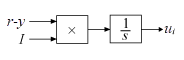
Within the block, the input signal u is multiplied by the externally supplied integrator gain, I, before integration. This implementation yields:
Thus, the integrator gain is included in the integral. Similarly, in the derivative term of the block, multiplication by the derivative gain precedes the differentiation, which causes the derivative gain D and the derivative setpoint weight c to be differentiated.
Programmatic Use
Block Parameter: ControllerParametersSource |
| Type: string, character vector |
Values: "internal", "external" |
Default: "internal" |
Specify a finite, real gain value for the proportional gain. When Controller form is:
Parallel— Proportional action is independent of the integral and derivative actions. For example, for a continuous-time 2-DOF PID controller in parallel form, the controller output u is:where r is the reference signal, y is the measured plant output signal, and b and c are the setpoint weights.
For a discrete-time 2-DOF controller in parallel form, the controller output is:
where the Integrator method and Filter method parameters determine α(z) and β(z), respectively.
Ideal— The proportional gain multiples the integral and derivative terms. For example, for a continuous-time 2-DOF PID controller in ideal form, the controller output is:For a discrete-time 2-DOF PID controller in ideal form, the transfer function is:
where the Integrator method and Filter method parameters determine α(z) and β(z), respectively.
Dependencies
To enable this parameter, set the Controller parameters Source to internal.
Programmatic Use
Block Parameter: P |
| Type: scalar, vector |
| Default: 1 |
Tunable: Yes
Specify a finite, real gain value for the integral gain.
Tunable: Yes
Dependencies
To enable this parameter, in the Main tab, set the controller-parameters
Source to internal, and set
Controller to a type that has integral action.
Programmatic Use
Block Parameter: I |
| Type: scalar, vector |
| Default: 1 |
For discrete-time controllers, specify a finite, real gain value for the integral gain multiplied by the sample time.
Note
PID tuning tools, such as the PID Tuner app and Closed-Loop PID Autotuner block, tune the gain I but not I*Ts. Therefore, multiply the integral gain value you obtain from a tuning tool by the sample time before you write it to this parameter.
When you use I*Ts instead of I, the block requires fewer calculations to perform integration. This improves the execution time of the generated code.
For continuous-time controllers, disable Use I*Ts and use the I parameter instead.
Tunable: No
Dependencies
To enable this parameter, in the Main tab, set the controller-parameters Source to internal, set Controller to a type that has integral action, and enable the Use I*Ts parameter.
Programmatic Use
Block Parameter: I |
| Type: scalar, vector |
| Default: 1 |
For discrete-time controllers with integral action, the block takes the integral gain as an input and multiplies it by the sample time internally as a part of performing the integration. If you enable this parameter, you explicitly specify integral gain multiplied by sample time as input (I*Ts) in place of the integral gain (I). Doing so reduces the number of internal calculations and is useful when you want to improve the execution time of your generated code.
If you have enabled signal tracking or the anti-windup mode back-calculation and you
enable I*Ts, then you must also set the tracking gain parameter
Kt to Kt*Ts and the back-calculation
coefficient Kb to Kb*Ts.
For continuous-time controllers, enabling this parameter has no effect on the integral gain.
Dependencies
To enable this parameter, set Controller to a controller type that has integral action.
Programmatic Use
Block Parameter: UseKiTs |
| Type: string, character vector |
Values: "on", "off" |
Default: "on" |
Specify a finite, real gain value for the derivative gain.
Tunable: Yes
Dependencies
To enable this parameter, in the Main tab, set the controller-parameters
Source to internal, and set
Controller to PID or
PD.
Programmatic Use
Block Parameter: D |
| Type: scalar, vector |
| Default: 0 |
Since R2024a
Select this option to specify the derivative of the plant signal y directly as an input ydot to the block. This is helpful when you have the derivative signal available in your model and want to skip the computation of the derivative inside the block.
Dependencies
To enable this option, select a controller type that has derivative action.
For discrete-time PID controllers only, clear this option to replace the filtered derivative with an unfiltered discrete-time differentiator. When you do so, the derivative term of the controller output becomes:
For continuous-time PID controllers, the derivative term is always filtered.
Dependencies
To enable this parameter, set Time domain to Discrete-time, and set Controller to a type that has a derivative term.
Programmatic Use
Block Parameter: UseFilter |
| Type: string, character vector |
Values: "on", "off" |
Default: "on" |
Specify a finite, real gain value for the filter coefficient. The filter coefficient determines the pole location of the filter in the derivative action of the block. The location of the filter pole depends on the Time domain parameter.
When Time domain is
Continuous-time, the pole location iss = -N.When Time domain is
Discrete-time, the pole location depends on the Filter method parameter.Filter Method Location of Filter Pole Forward EulerBackward EulerTrapezoidal
The block does not support N = Inf (ideal unfiltered derivative). When the Time domain is Discrete-time, you can clear Use filtered derivative to remove the derivative filter.
Dependencies
To enable this parameter, in the Main tab, set the controller-parameters
Source to
internal and set
Controller to
PID or
PD.
Programmatic Use
Block Parameter: N |
| Type: scalar, vector |
| Default: 100 |
Tunable: Yes
Setpoint weight on the proportional term of the controller. The proportional term of a 2-DOF controller output is P(br–y), where r is the reference signal and y is the measured plant output. Setting b to 0 eliminates proportional action on the reference signal, which can reduce overshoot in the system response to step changes in the setpoint. Changing the relative values of b and c changes the balance between disturbance rejection and setpoint tracking.
Tunable: Yes
Dependencies
To enable this parameter, in the Main tab, set the controller-parameters
Source to internal.
Programmatic Use
Block Parameter: b |
| Type: scalar, vector |
| Default: 1 |
Setpoint weight on the derivative term of the controller. The derivative term of a 2-DOF controller acts on cr–y, where r is the reference signal and y is the measured plant output. Thus, setting c to 0 eliminates derivative action on the reference signal, which can reduce transient response to step changes in the setpoint. Setting c to 0 can yield a controller that achieves both effective disturbance rejection and smooth setpoint tracking without excessive transient response. Changing the relative values of b and c changes the balance between disturbance rejection and setpoint tracking.
Tunable: Yes
Dependencies
To enable this parameter, in the Main tab, set the controller-parameters
Source to internal and set
Controller to a type that has derivative action.
Programmatic Use
Block Parameter: c |
| Type: scalar, vector |
| Default: 1 |
If you have Simulink Control Design software, you can automatically tune the PID coefficients when they are internal to the block. To do so, use this parameter to select a tuning tool, and click Tune.
Transfer Function Based (PID Tuner App)Use PID Tuner, which lets you interactively tune PID coefficients while examining relevant system responses to validate performance. PID Tuner can tune all the coefficients P, I, D, and N, and the setpoint coefficients b and c. By default, PID Tuner works with a linearization of your plant model. For models that cannot be linearized, you can tune PID coefficients against a plant model estimated from simulated or measured response data. For more information, see Design Two-Degree-of-Freedom PID Controllers (Simulink Control Design).
Frequency Response BasedUse Frequency Response Based PID Tuner, which tunes PID controller coefficients based on frequency-response estimation data obtained by simulation. This tuning approach is especially useful for plants that are not linearizable or that linearize to zero. Frequency Response Based PID Tuner tunes the coefficients P, I, D, and N, but does not tune the setpoint coefficients b and c. For more information, see Design PID Controller from Plant Frequency-Response Data (Simulink Control Design).
Both of these tuning methods assume a single-loop control configuration. Simulink Control Design software includes other tuning approaches that suit more complex configurations. For information about other ways to tune a PID Controller block, see Choose a Control Design Approach (Simulink Control Design).
Dependencies
To enable this parameter, in the Main tab, set the
controller-parameters Source to
internal.
Zero-crossing detection can accurately locate signal discontinuities without resorting to excessively small time steps that can lead to lengthy simulation times. If you select Limit output or activate External reset in your PID Controller block, activating zero-crossing detection can reduce computation time in your simulation. Selecting this parameter activates zero-crossing detection:
At initial-state reset
When entering an upper or lower saturation state
When leaving an upper or lower saturation state
For more information about zero-crossing detection, see Zero-Crossing Detection.
Programmatic Use
Block Parameter: ZeroCross |
| Type: string, character vector |
Values: "on", "off" |
Default: "on" |
Initialization
Simulink uses initial conditions to initialize the integrator and derivative-filter (or the unfiltered derivative) output at the start of a simulation or at a specified trigger event. (See the External reset parameter.) These initial conditions determine the initial block output. Use this parameter to select how to supply the initial condition values to the block.
internalSpecify the initial conditions using the Integrator Initial condition and Filter Initial condition parameters. If Use filtered derivative is not selected, use the Differentiator parameter to specify the initial condition for the unfiltered differentiator instead of a filter initial condition.
externalSpecify the initial conditions externally using block inputs. Additional input ports Io and Do appear on the block. If Use filtered derivative is not selected, supply the initial condition for the unfiltered differentiator at Do instead of a filter initial condition.
Programmatic Use
Block Parameter:
InitialConditionSource |
| Type: string, character vector |
Values:
"internal", "external" |
Default:
"internal" |
Simulink uses the integrator initial condition to initialize the integrator at the start of a simulation or at a specified trigger event (see External reset). The integrator initial condition and the filter initial condition determine the initial output of the PID controller block.
The integrator initial condition cannot be NaN or Inf.
Dependencies
To use this parameter, in the Initialization tab, set
Source to internal, and set
Controller to a type that has integral action.
Programmatic Use
Block Parameter: InitialConditionForIntegrator |
| Type: scalar, vector |
| Default: 0 |
Simulink uses the filter initial condition to initialize the derivative filter at the start of a simulation or at a specified trigger event (see External reset). The integrator initial condition and the filter initial condition determine the initial output of the PID controller block.
The filter initial condition cannot be NaN or Inf.
Dependencies
To use this parameter, in the Initialization tab, set
Source to internal, and use a
controller that has a derivative filter.
Programmatic Use
Block Parameter: InitialConditionForFilter |
| Type: scalar, vector |
| Default: 0 |
When you use an unfiltered derivative, Simulink uses this parameter to initialize the differentiator at the start of a simulation or at a specified trigger event (see External reset). The integrator initial condition and the derivative initial condition determine the initial output of the PID controller block.
The derivative initial condition cannot be NaN or Inf.
Dependencies
To use this parameter, set Time domain to Discrete-time, clear the Use filtered derivative check box, and in the Initialization tab, set Source to internal.
Programmatic Use
Block Parameter: DifferentiatorICPrevScaledInput |
| Type: scalar, vector |
| Default: 0 |
Use this parameter to specify whether to apply the Integrator Initial condition and Filter Initial condition parameter to the corresponding block state or output. You can change this parameter at the command line only, using set_param to set the InitialConditionSetting parameter of the block.
AutoUse this option in all situations except when the block is in a triggered subsystem or a function-call subsystem and simplified initialization mode is enabled.
OutputUse this option when the block is in a triggered subsystem or a function-call subsystem and simplified initialization mode is enabled.
For more information about the Initial condition setting parameter, see the Discrete-Time Integrator block.
This parameter is only accessible through programmatic use.
Programmatic Use
Block Parameter: InitialConditionSetting |
| Type: string, character vector |
Values:
"Auto", "Output" |
Default:
"Auto" |
Specify the trigger condition that causes the block to reset the integrator and filter to initial conditions. (If Use filtered derivative is not selected, the trigger resets the integrator and differentiator to initial conditions.) Selecting any option other than none enables the Reset port on the block for the external reset signal.
noneThe integrator and filter (or differentiator) outputs are set to initial conditions at the beginning of simulation, and are not reset during simulation.
risingReset the outputs when the reset signal has a rising edge.
fallingReset the outputs when the reset signal has a falling edge.
eitherReset the outputs when the reset signal either rises or falls.
levelReset the outputs when the reset signal either:
Is nonzero at the current time step
Changes from nonzero at the previous time step to zero at the current time step
This option holds the outputs to the initial conditions while the reset signal is nonzero.
Dependencies
To enable this parameter, set Controller to a type that has derivative or integral action.
Programmatic Use
Block Parameter: ExternalReset |
| Type: string, character vector |
Values:
"none",
"rising",
"falling",
"either","level" |
Default: "none" |
Select to force Simulink and Simulink Control Design linearization commands to ignore any reset mechanism specified in the External reset parameter. Ignoring reset states allows you to linearize a model around an operating point even if that operating point causes the block to reset.
Programmatic Use
Block Parameter: IgnoreLimit |
| Type: string, character vector |
Values: "off", "on" |
Default: "off" |
Signal tracking lets the block output follow a tracking signal that you provide at the TR port. When signal tracking is active, the difference between the tracking signal and the block output is fed back to the integrator input with a gain Kt, specified by the Tracking gain (Kt) parameter. Signal tracking has several applications, including bumpless control transfer and avoiding windup in multiloop control structures.
Bumpless control transfer
Use signal tracking to achieve bumpless control transfer in systems that switch between two controllers. Suppose you want to transfer control between a PID controller and another controller. To do so, connecting the controller output to the TR input as shown in the following illustration.
![]()
For more information, see Bumpless Control Transfer with a Two-Degree-of-Freedom PID Controller.
Multiloop control
Use signal tracking to prevent block windup in multiloop control approaches. For an example illustrating this approach with a 1DOF PID controller, see Prevent Block Windup in Multiloop Control.
Dependencies
To enable this parameter, set Controller to a type that has integral action.
Programmatic Use
Block Parameter: TrackingMode |
| Type: string, character vector |
Values: "off", "on" |
Default: "off" |
When you select Enable tracking mode, the difference between the signal TR and the block output is fed back to the integrator input with a gain Kt. Use this parameter to specify the gain in that feedback loop.
For discrete-time controllers, if you select the Use I*Ts
parameter of the block, then set this parameter to the value Kt*Ts,
where Kt is the desired gain and Ts is the sample
time.
Dependencies
To enable this parameter, select Enable tracking mode.
Programmatic Use
Block Parameter: Kt |
| Type: scalar |
| Default: 1 |
Saturation
Output saturation
Activating this option limits the block output, so that you do not need a separate Saturation block after the controller. It also allows you to activate the anti-windup mechanism built into the block (see the Anti-windup method parameter). Specify the output saturation limits using the Lower limit and Upper limit parameters. You can also specify the saturation limits externally as block input ports.
Programmatic Use
Block Parameter: LimitOutput |
| Type: string, character vector |
Values: "off", "on" |
Default: "off" |
Use this parameter to specify how to supply the upper and lower saturation limits of the block output.
internalSpecify the output saturation limits using the Upper limit and Lower limit parameters.
externalSpecify the output saturation limits externally using block input ports. The additional input ports up and lo appear on the block. You can use the input ports to implement the upper and lower output saturation limits determined by logic or other calculations in the Simulink model and passed to the block.
Programmatic Use
Block Parameter:
SatLimitsSource |
| Type: string, character vector |
Values:
"internal", "external" |
Default:
"internal" |
Specify the upper limit for the block output. The block output is held at the Upper saturation limit whenever the weighted sum of the proportional, integral, and derivative actions exceeds that value.
Dependencies
To enable this parameter, select Limit output.
Programmatic Use
Block Parameter: UpperSaturationLimit |
| Type: scalar |
Default: Inf |
Specify the lower limit for the block output. The block output is held at the Lower saturation limit whenever the weighted sum of the proportional, integral, and derivative actions goes below that value.
Dependencies
To enable this parameter, select Limit output.
Programmatic Use
Block Parameter: LowerSaturationLimit |
| Type: scalar |
Default: -Inf |
Force Simulink and Simulink Control Design linearization commands to ignore block output limits specified in the Upper limit and Lower limit parameters. Ignoring output limits allows you to linearize a model around an operating point even if that operating point causes the block to exceed the output limits.
Dependencies
To enable this parameter, select the Limit output parameter.
Programmatic Use
Block Parameter: LinearizeAsGain |
| Type: string, character vector |
Values: "off", "on" |
Default: "off" |
When you select Limit output and the weighted sum of the controller components exceeds the specified output limits, the block output holds at the specified limit. However, the integrator output can continue to grow (integrator windup), increasing the difference between the block output and the sum of the block components. In other words, the internal signals in the block can be unbounded even if the output appears bounded by saturation limits. Without a mechanism to prevent integrator windup, two results are possible:
If the sign of the signal entering the integrator never changes, the integrator continues to integrate until it overflows. The overflow value is the maximum or minimum value for the data type of the integrator output.
If the sign of the signal entering the integrator changes once the weighted sum has grown beyond the output limits, it can take a long time to unwind the integrator and return the weighted sum within the block saturation limit.
In either case, controller performance can suffer. To combat the effects of windup without an anti-windup mechanism, it may be necessary to detune the controller (for example, by reducing the controller gains), resulting in a sluggish controller. To avoid this problem, activate an anti-windup mechanism using this parameter.
noneDo not use an anti-windup mechanism.
back-calculationUnwind the integrator when the block output saturates by feeding back to the integrator the difference between the saturated and unsaturated control signal. The following diagram represents the back-calculation feedback circuit for a continuous-time controller. To see the actual feedback circuit for your controller configuration, right-click the block and select Edit Mask > Look Inside Mask.
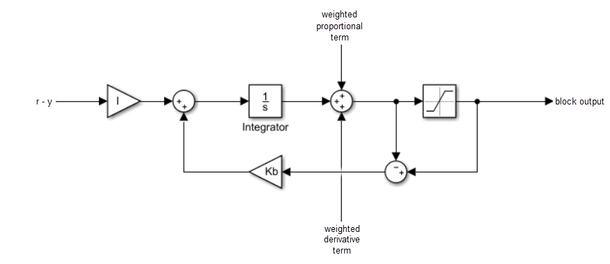
Use the Back-calculation coefficient (Kb) parameter to specify the gain of the anti-windup feedback circuit. It is usually satisfactory to set
Kb = I, or for controllers with derivative action,Kb = sqrt(I*D). Back-calculation can be effective for plants with relatively large dead time [1].clampingClamping is sometimes referred to as conditional integration.
Integration stops when both of the following conditions are true:
The sum of the block components exceeds the output limits.
The integrator input and saturation block input have the same sign.
Integration resumes when either of these conditions is no longer true.
Clamping can be useful for plants with relatively small dead times, but can yield a poor transient response for large dead times [1].
external(since R2024b)The built-in anti-windup methods rely on the sum of the block components exceeding the specified block output limits. If your application has saturations or limits downstream of the PID controller blocks, you can use the extAW input port to implement a custom anti-windup logic. The block also provides the signal before the integrator at the preInt output port that you can use as input to your custom algorithm.
Dependencies
To enable this parameter, select the Limit output parameter.
Programmatic Use
Block Parameter:
AntiWindupMode |
| Type: string, character vector |
Values:
"none",
"back-calculation","clamping",
"external" |
Default:
"none" |
The back-calculation anti-windup method unwinds the integrator when the
block output saturates. It does so by feeding back to the integrator the difference
between the saturated and unsaturated control signal. Use the Back-calculation
coefficient (Kb) parameter to specify the gain of the anti-windup
feedback circuit. For more information, see the Anti-windup method
parameter.
For discrete-time controllers, if you select the Use I*Ts
parameter of the block, then set this parameter to the value Kb*Ts,
where Kb is the desired coefficient and Ts is the
sample time.
Dependencies
To enable this parameter, select the Limit output parameter, and set the
Anti-windup method parameter to
back-calculation.
Programmatic Use
Block Parameter: Kb |
| Type: scalar |
| Default: 1 |
Integrator saturation
Enable this parameter to limit the integrator output to be within a specified range. When the integrator output reaches the limits, the integral action turns off to prevent integral windup. Specify the saturation limits using the Lower limit and Upper limit parameters.
Dependencies
To enable this parameter, set Controller to a controller type that has integral action.
Programmatic Use
Block Parameter: LimitIntegratorOutput |
| Type: string, character vector |
Values: "off", "on" |
Default: "off" |
Specify the upper limit for the integrator output. The integrator output is held at this value whenever it would otherwise exceed this value.
Dependencies
To enable this parameter, under Integrator saturation, select Limit output.
Programmatic Use
Block Parameter: UpperIntegratorSaturationLimit |
| Type: scalar |
Default: Inf |
Specify the lower limit for the integrator output. The integrator output is held at this value whenever it would otherwise go below this value.
Dependencies
To enable this parameter, under Integrator saturation, select Limit output.
Programmatic Use
Block Parameter: LowerIntegratorSaturationLimit |
| Type: scalar |
Default: -Inf |
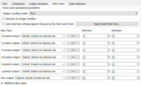
Data Types
The parameters in this tab are primarily of use in fixed-point code generation using Fixed-Point Designer™. They define how numeric quantities associated with the block are stored and processed when you generate code.
If you need to configure data types for fixed-point code generation, click Open Fixed-Point Tool and use that tool to configure the rest of the parameters in the tab. For information about using Fixed-Point Tool, see Autoscaling Data Objects Using the Fixed-Point Tool (Fixed-Point Designer).
After you use Fixed-Point Tool, you can use the parameters in this tab to make adjustments to fixed-point data-type settings if necessary. For each quantity associated with the block, you can specify:
Floating-point or fixed-point data type, including whether the data type is inherited from upstream values in the block.
The minimum and maximum values for the quantity, which determine how the quantity is scaled for fixed-point representation.
For assistance in selecting appropriate values, click ![]() to open the Data Type Assistant for the corresponding quantity. For more information, see Specify Data Types Using Data Type Assistant.
to open the Data Type Assistant for the corresponding quantity. For more information, see Specify Data Types Using Data Type Assistant.
The specific quantities listed in the Data Types tab vary depending on how you configure the PID controller block. In general, you can configure data types for the following types of quantities:
Product output — Stores the result of a multiplication carried out under the block mask. For example, P product output stores the output of the gain block that multiplies the block input with the proportional gain P.
Parameter — Stores the value of a numeric block parameter, such as P, I, or D.
Block output — Stores the output of a block that resides under the PID controller block mask. For example, use Integrator output to specify the data type of the output of the block called Integrator. This block resides under the mask in the Integrator subsystem, and computes integrator term of the controller action.
Accumulator — Stores values associated with a sum block. For example, SumI2 Accumulator sets the data type of the accumulator associated with the sum block SumI2. This block resides under the mask in the Back Calculation subsystem of the Anti-Windup subsystem.
In general, you can find the block associated with any listed parameter by looking under the
PID Controller block mask and examining its subsystems. You can also use the Model Explorer
to search under the mask for the listed parameter name, such as SumI2.
(See Model
Explorer.)
Matching Input and Internal Data Types
By default, all data types in the block are set to Inherit: Inherit via internal rule. With this setting, Simulink chooses data types to balance numerical accuracy, performance, and generated code size, while accounting for the properties of the embedded target hardware.
Under some conditions, incompatibility can occur between data types within the block. For
instance, in continuous time, the Integrator block under the mask can accept only signals of
type double. If the block input signal is a type that cannot be
converted to double, such as uint16,
the internal rules for type inheritance generate an error when you generate code.
To avoid such errors, you can use the Data Types settings to force a data type conversion. For
instance, you can explicitly set P product output, I product
output, and D product output to
double, ensuring that the signals reaching the
continuous-time integrators are of type double.
In general, it is not recommended to use the block in continuous time for code generation applications. However, similar data type errors can occur in discrete time, if you explicitly set some values to data types that are incompatible with downstream signal constraints within the block. In such cases, use the Data Types settings to ensure that all data types are internally compatible.
Fixed-Point Operational Parameters
Specify the rounding mode for fixed-point operations. For more information, see Rounding Modes (Fixed-Point Designer).
Block parameters always round to the nearest representable value. To control the rounding of a block parameter, enter an expression using a MATLAB® rounding function into the mask field.
Programmatic Use
To set the block parameter value programmatically, use
the set_param function.
| Parameter: | RndMeth |
| Values: | 'Floor' (default) | 'Ceiling' | 'Convergent' | 'Nearest' | 'Round' | 'Simplest' | 'Zero' |
Specify whether overflows saturate or wrap.
on— Overflows saturate to either the minimum or maximum value that the data type can represent.off— Overflows wrap to the appropriate value that the data type can represent.
For example, the maximum value that the signed 8-bit integer int8
can represent is 127. Any block operation result greater than this maximum value causes
overflow of the 8-bit integer.
With this parameter selected, the block output saturates at 127. Similarly, the block output saturates at a minimum output value of -128.
With this parameter cleared, the software interprets the overflow-causing value as
int8, which can produce an unintended result. For example, a block result of 130 (binary 1000 0010) expressed asint8is -126.
Tips
Consider selecting this parameter when your model has a possible overflow and you want explicit saturation protection in the generated code.
Consider clearing this parameter when you want to optimize efficiency of your generated code. Clearing this parameter also helps you to avoid overspecifying how a block handles out-of-range signals. For more information, see Troubleshoot Signal Range Errors.
When you select this parameter, saturation applies to every internal operation on the block, not just the output or result.
In general, the code generation process can detect when overflow is not possible. In this case, the code generator does not produce saturation code.
Programmatic Use
To set the block parameter value programmatically, use
the set_param function.
| Parameter: | SaturateOnIntegerOverflow |
| Values: | 'off' (default) | 'on' |
Select this parameter to prevent the fixed-point tools from overriding the data types you specify on this block. For more information, see Lock the Output Data Type Setting (Fixed-Point Designer).
Programmatic Use
Block Parameter: LockScale |
| Type: character vector |
Values: 'off' | 'on' |
Default: 'off' |
State Attributes
The parameters in this tab are primarily of use in code generation.
Assign a unique name to the state associated with the integrator or the filter, for continuous-time PID controllers. (For information about state names in a discrete-time PID controller, see the State name parameter.) The state name is used, for example:
For the corresponding variable in generated code
As part of the storage name when logging states during simulation
For the corresponding state in a linear model obtain by linearizing the block
A valid state name begins with an alphabetic or underscore character, followed by alphanumeric or underscore characters.
Dependencies
To enable this parameter, set Time domain to Continuous-time.
Programmatic Use
Parameter: IntegratorContinuousStateAttributes, FilterContinuousStateAttributes |
| Type: character vector |
Default: '' |
Assign a unique name to the state associated with the integrator or the filter, for discrete-time PID controllers. (For information about state names in a continuous-time PID controller, see the State name (e.g., 'position') parameter.)
A valid state name begins with an alphabetic or underscore character, followed by alphanumeric or underscore characters. The state name is used, for example:
For the corresponding variable in generated code
As part of the storage name when logging states during simulation
For the corresponding state in a linear model obtain by linearizing the block
For more information about the use of state names in code generation, see C Data Code Interface Configuration for Model Interface Elements (Simulink Coder).
Dependencies
To enable this parameter, set Time domain to Discrete-time.
Programmatic Use
Parameter: IntegratorStateIdentifier, FilterStateIdentifier |
| Type: string, character vector |
Default: "" |
Select this parameter to require that the discrete-time integrator or filter state name resolves to a Simulink signal object.
Dependencies
To enable this parameter for the discrete-time integrator or filter state:
Set Time domain to
Discrete-time.Specify a value for the integrator or filter State name.
Set the model configuration parameter Signal resolution to a value other than
None.
Programmatic Use
Block Parameter: IntegratorStateMustResolveToSignalObject, FilterStateMustResolveToSignalObject |
| Type: string, character vector |
Values: "off", "on" |
Default: "off" |
Block Characteristics
Data Types |
|
Direct Feedthrough |
|
Multidimensional Signals |
|
Variable-Size Signals |
|
Zero-Crossing Detection |
|
More About
A 2-DOF PID controller can be interpreted as a PID controller with a prefilter, or a PID controller with a feedforward element.
In parallel form, a two-degree-of-freedom PID controller can be equivalently modeled by the following block diagram, where C is a single degree-of-freedom PID controller and F is a prefilter on the reference signal.

Ref is the reference signal, y is the feedback from the measured system output, and u is the controller output. For a continuous-time 2-DOF PID controller in parallel form, the transfer functions for F and C are
where b and c are the setpoint weights.
For a 2-DOF PID controller in ideal form, the transfer functions are
A similar decomposition applies for a discrete-time 2-DOF controller.
Alternatively, the parallel two-degree-of-freedom PID controller can be modeled by the following block diagram.

In this realization, Q acts as feedforward conditioning on the reference signal. For a continuous-time 2-DOF PID controller in parallel form, the transfer function for Q is
For a 2-DOF PID controller in ideal form, the transfer function is
The transfer functions for C are the same as in the filter decomposition.
A similar decomposition applies for a discrete-time 2-DOF controller.
References
[1] Visioli, A., "Modified Anti-Windup Scheme for PID Controllers," IEE Proceedings - Control Theory and Applications, Vol. 150, Number 1, January 2003
Extended Capabilities
Version History
Introduced in R2009bSee Also
PID Controller | Gain | Integrator | Derivative | Discrete PID Controller (2DOF)