Implement Variations in Separate Hierarchy Using Variant Subsystems
This example shows how to configure and use a Variant Subsystem block in Simulink®. The Variant Subsystem block is a hierarchical variant block. The block allows you to encapsulate multiple implementations or variations of a system component in a separate hierarchy in the model. Each variation of the component represented within a Variant Subsystem block is referred to as a choice. Only one of the variant choices within the Variant subsystem block can be active during model execution. You can use a combination of Subsystem blocks, Model blocks, or Create and Use Referenced Subsystems in Models blocks to represent the choices within the Variant Subsystem block.
For information on the block and its parameters, see Variant Subsystem.
Explore the Model
Open the model
slexVariantSubsystems. A variant subsystem block,Controller, encapsulates two different implementations of the controller component in the system.
open_system('slexVariantSubsystems');

Open the variant subsystem
Controller. Two Subsystem blocks represent the two possible variations of theControllercomponent. The first choice is aLinear Controller, and the second choice is aNonlinear Controller. Note that there are no drawn connections between the blocks inside the Variant Subsystem block. Simulink automatically wires the active variant to the Inport and Outport blocks of the Variant Subsystem block during simulation and disables the inactive ports.
open_system('slexVariantSubsystems/Controller');

Open the Block Parameters dialog box for the
Controllerblock. The Variant choices table lists the choices of the variant subsystem. Each variant choice in theControllerblock is associated with a variant control. Here, the variant controls areV == 1andV == 2. Simulink determines the active choice of the variant subsystem by evaluating the variant controls of all the choices. When a variant control evaluates totrue, Simulink activates the variant choice that corresponds to that variant control and disables the inactive choices. So, while each variant choice is associated with a variant control, only one variant control must evaluate totrue. This allows you to swap the active and inactive choice in the variant subsystem without modifying the model structure.

Configure a Variant Subsystem Block
In this model, the Controller variant subsystem is preconfigured with two subsystems, Linear Controller and Nonlinear Controller, as variant choices. To add more Variant Subsystem blocks to this model and configure the blocks, perform these steps:
Add a Variant Subsystem block to your model using the Simulink Library Browser or the Quick Insert menu and name the block. This block serves as the container for the variant choices.
To open the Variant Subsystem block and view its variant choices, double-click the block and then click the Up to parent button located in the toolbar at the top of the Simulink model canvas. The Variant Subsystem block, by default, is a template preconfigured with two Subsystem blocks to represent the variant choices.
Inside the Variant Subsystem block, add Inport and Outport blocks so that they match the inputs into and outputs from the Variant Subsystem block.
Name the variant choice blocks.
NOTE:
You can add only Inport, Outport, Subsystem, Model, and Subsystem Reference blocks inside a Variant Subsystem block. You can pass control signals through data ports.
If your variant choices have different numbers of input and output ports, see Represent Variant Choices That Have Different Interfaces.
When you add a Variant Subsystem block to your model, the Variant activation time parameter is set to
update diagramand the Propagate conditions outside of variant subsystem parameter is set tooffby default.

Types of Variant Choices in Variant Subsystem
You can add subsystems, Simulink models, and subsystem references as variant choices in a variant subsystem.
Include Subsystem Block as Variant Choice
You can add a Subsystem block as a variant choice from the Block Parameters dialog box of the Variant Subsystem block or using the action bar in the Simulink Editor from inside the variant subsystem. Simulink creates an empty Subsystem block with the same number of input and output ports as the containing Variant Subsystem block.
a. Using Block Parameters Dialog Box
Open the block parameter dialog box of the Variant Subsystem block. Right-click the badge on the Variant Subsystem block and select Block Parameters (Subsystem).
The Variant choices in the block parameter dialog box shows the variant choices that you added. You can use buttons to the left of the table to add or modify elements in the table.
To include a Subsystem block as a new variant choice inside the Variant Subsystem, click the Create and add a new subsystem variant choice button to the left of the Variant choices table.
Open the new Subsystem block and add the model elements that represent a variant choice.

b. Using Action Bar
Double-click the Variant Subsystem block and then click the Up to Parent button located in the toolbar at the top of the Simulink model canvas.
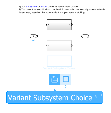
Drag a selection box around an empty area inside the Variant Subsystem block. The action bar shows subsystem insertion options that are based on the type of subsystem choices in the block.
From the action bar, select the Variant Subsystem Choice option to add a subsystem block.
Open the new Subsystem block and add the model elements that represent a variant choice.
NOTE:
If your variant choices have different numbers of input and output ports, see Represent Variant Choices That Have Different Interfaces.
You can use conditionally executed subsystems such as Enabled, Triggered, Reset, and the Function-Call subsystems as variant choices within the Variant Subsystem block. For more information, see Propagate Variant Conditions to Control Execution of Conditional Subsystems.
When you prototype variants, you can create empty Subsystem blocks with no inputs or outputs inside the Variant Subsystem block. The empty subsystem recreates the situation in which that subsystem is inactive without the need for completely modeling the variant choice.
![]()
Include Simulink Model as Variant Choice
To include a Simulink model (Model block) as a new variant choice inside the variant subsystem, click the Create and add a new model variant choice button to the left of the Variant choices table. Simulink creates an unresolved Model block in the Variant Subsystem block.
Double-click the unresolved Model block. In the Model name box, enter the name of the model you want to use as a model variant choice and click OK.
NOTE: The referenced model must have the same number of input and output ports as the containing Variant Subsystem block. If your model has different number of input and output ports, see Represent Variant Choices That Have Different Interfaces.

Include Subsystem Reference as Variant Choice
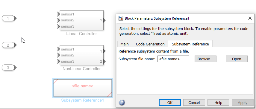
To include a subsystem reference as a new variant choice inside the variant subsystem, add a Subsystem Reference block using the Simulink Library Browser or the Quick Insert menu. Simulink creates an empty Subsystem Reference block in the Variant Subsystem block.
Double-click the Subsystem Reference block. In the Block Parameters dialog box, specify the subsystem block diagram file and click OK.
Choose a Variant Control Mode
You must associate each variant choice in a model with a variant control that determines if the choice is active or inactive. You can choose the mode in which you want to specify the variant controls using the Variant control mode block parameter. The Variant control mode parameter for the Controller block in this example is set to expression. In this mode, you can specify the variant control for a choice as a Boolean condition expression, a Simulink.VariantExpression object, the default variant choice, or an empty choice. For information on the different types of variant control modes, see Variant Control Modes in Variant Blocks.
Use Variant Controls to Activate and Switch Between Variant Choices
In this model, the variant control V for each choice is a MATLAB® scalar variable. You can change V to any of these types based on your requirement as described in Use Variant Control Variables in Variant Blocks.
Since V is set to 1, the Linear Controller gets activated by default. To switch the active choice to NonLinear Controller, set V = 2 in the base workspace and simulate the model.
Specify Default Variant Choice: When the variant control mode is set to expression, you can specify at most one variant choice as the default for the model. Simulink evaluates the variant controls and verifies that only one variant choice is active during simulation. If none of the variant controls evaluate to true, Simulink uses the default variant for simulation and code generation. To set a variant choice as the default, select the (default) keyword in the Variant control expression column for that choice.
Specify Empty Variant Choice: If you added an empty variant choice, you can either specify a variant activation condition for the choice or comment out the existing variant condition by placing a % symbol before the condition. If this variant choice is active during simulation, Simulink ignores the empty variant choice. However, Simulink continues to execute block callbacks inside the empty variant choices.
![]()
For information on other ways to define variant controls, see Use Variant Control Variables in Variant Blocks.
Choose a Variant Activation Time
The Variant activation time that you specify for the Variant Subsystem block determines the stage when Simulink sets the active choice for the block. This parameter also determines how the active and inactive choices participate in the simulation and code generation workflows.
For the Controller block, this parameter is set to update diagram. So, Simulink sets the active choice at the start of the model compilation stage and the inactive choices are removed. When you execute the model, only the active choice is analyzed for consistency. Generated code contains only the active choice. For information on other variant activation times, see Activate Variant During Different Stages of Simulation and Code Generation Workflow.
Represent Variant Choices That Have Different Interfaces
In this example, the two variant choices, Linear Controller and NonLinear Controller, have the same number of input and output ports as the Controller variant subsystem. The blocks that represent the variant choices can also have input and output ports that differ in number from the input and output ports on the parent Variant Subsystem block. The Variant Subsystem block can adapt its interface based on the activeness of the underlying blocks. This allows you to model component variations that do not have a similar interface. In this case, these conditions must be satisfied by the variant choices:
The Allow flexible interface parameter must be set to
'on'.The variant choices must have same set of inports as the Variant Subsystem container block or it must be a subset of ports on the container block.
The variant choices must have same set of outports as the Variant Subsystem container block or it must be a subset of ports on the container block.
If the Variant Subsystem container block has control ports, the type of control port blocks in all the variant choices must be same as the Variant Subsystem block. For example, you cannot use Enabled Subsystem and Function-Call Subsystem blocks as choices within a Variant Subsystem block. The control port on the Variant Subsystem block and the corresponding control ports on its variant choices must have the same name. For example, if the name of the control port on the Variant Subsystem is
fcn, then the name of the corresponding control ports on all its variant choices must also befcn.
For an example, see Adaptive Interface for Variant Subsystems.
When simulating models, a Variant Subsystem or Variant Assembly Subsystem block may have missing or unused ports. This can occur when a Variant Subsystem does not have a port that is present in one of its variant choices, or conversely, has a port that is not used by any variant choice. To address this, you can use the Simulink.VariantUtils.updateVariantSubsystemPorts
Zero Active Variant Controls for Variant Subsystem
The Built-in empty choice and the Built-in passthrough choice parameters on the Variant Subsystem block determine whether the block allows simulation even if none of the variant choices are active.
When you select the Built-in empty choice parameter and there is no active variant choice, Simulink disconnects the variant choices of Variant Subsystem block, thus removing the variant regions completely from the model. The inactive outports of the subsystem output a zero.
When you select the Built-in passthrough choice parameter and there is no active variant choice, Simulink bypasses the variant choices of the Variant Subsystem block. Only the input and output ports remain active to pass the values from input to output ports.
These parameters are available only if there are no (default) variant choices in the variant subsystem and if you set Variant control mode to expression.
Propagate Variant Conditions Outside Variant Subsystem
During simulation, Simulink automatically propagates variant conditions from variant blocks to connecting blocks to determine which components of the model remain active. For a variant subsystem, the variant conditions defined on the choices do not propagate outside the Variant Subsystem block by default. To enable this, you can set the Propagate conditions outside of variant subsystem parameter on the Variant Subsystem block.
When you select the Propagate conditions outside of variant subsystem parameter, Simulink propagates the variant condition of the underlying blocks to the Variant Subsystem container block so that the subsystem can adapt its interface to the state of the underlying blocks. Ports that are mapped to the ports on the active choice becomes active. Ports that are mapped to the ports on the inactive choice becomes inactive. Selecting this option ensures that the components outside of the Variant Subsystem are aware of the active and inactive state of blocks within the Variant Subsystem block. For more information, see Propagate Variant Conditions to Define Variant Regions Outside Variant Subsystems to Promote Consistency and Reduce Errors.
Convert to Variant Subsystem Block
In the Simulink Editor, you can convert these blocks to a Variant Subsystem block:
Subsystem block
Model block
Conditionally executed subsystems
To do so, right-click the block and in the context menu click Subsystem & Model Reference > Convert to > Variant Subsystem.
You can also convert these blocks to a Variant Subsystem block programmatically using the Simulink.VariantUtils.convertToVariantSubsystem method.
See Also
Working with Variant Choices | Propagate Variant Conditions to Control Execution of Conditional Subsystems
Topics
- Generate Code for Variant Subsystem Blocks (Simulink Coder)