Bus Assignment
Assign new values to specified bus elements
Libraries:
Simulink /
Signal Routing
HDL Coder /
Signal Routing
Description
The Bus Assignment block assigns new values to selected bus elements. Use a Bus Assignment block to change element values without extracting elements and reassembling the bus with the desired elements. A Bus Assignment block simplifies updating a bus to reflect the processing that occurs in a separate component, such as a subsystem or referenced model.
The Bus Assignment block assigns elements connected to the assignment ports to specified elements of the bus connected to the bus input port. The block replaces the elements previously assigned to those elements. The change does not affect the composition of the bus. The change affects only the values of the elements. Elements not replaced are unaffected by the replacement of other elements.
The elements to which you assign values can be nonbus signals or buses, including arrays of buses, as long as they are elements of the input bus. The new values must match the attributes of the elements in the original bus.
By default, the software repairs broken selections for a Bus Assignment block
that are due to upstream bus hierarchy changes. A warning notifies you when a repair modifies
the model. To prevent the software from making these repairs automatically, set the
Repair bus selections configuration
parameter to Error without repair.
Examples
To replace the value of a bus element, use a Bus Assignment block. You do not need to use Bus Selector and Bus Creator blocks to change the value of a bus element.
Open and compile the example model named BusAssignment. To compile the model, in the Simulink® Toolstrip, on the Modeling tab, click Update Model. Compiling the model updates the line styles, which you can use to visually identify buses.
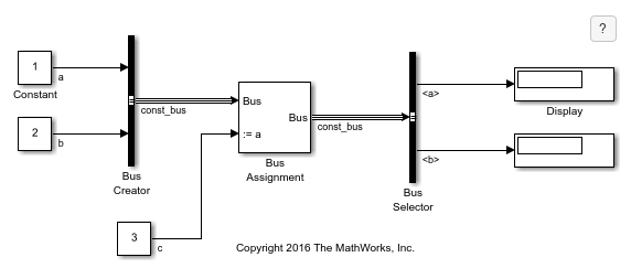
The Bus Assignment block has two input ports.
The first input port receives a bus named
constants.The second input port receives a signal named
c.
Double-click the Bus Assignment block to open a dialog box with assignment options.
The Block Parameters dialog box lists the elements available for assignment in the Elements in the bus list. In this model, elements a and b are available for assignment.
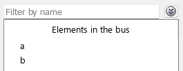
Element a also appears in the Elements that are being assigned list, which indicates that the element is selected for assignment.
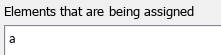
To indicate the element that corresponds with an assignment port, the port label on the block icon includes the element name. For element a, the port label is :=a.
![]()
Signal c connects to the assignment port for element a. The Bus Assignment block replaces the value of element a, which is 1, with the value of signal c, which is 3.
To display the new value of element a and the unchanged value of element b, the Bus Selector block selects elements a and b, and these elements connect to Display blocks.
To populate the Display blocks, in the Simulink Toolstrip, on the Modeling tab, click Run.
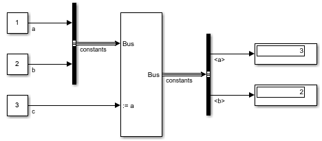
The Display blocks show the value of the elements after assignment.
Element
ahas a value of 3, which is its new value from the Bus Assignment block.Element
bhas a value of 2, which is its original value.
You can select additional elements for assignment by selecting an element under Elements in the bus then clicking Select. The Bus Assignment block adds an input port for each additional element to which you want to assign a new value. The new input ports let you connect the signals that you want to assign to the additional elements.
Extended Examples
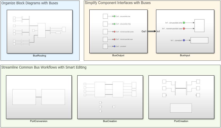
Simulink Bus Capabilities
Work with buses in components, simplify component interfaces, and streamline common bus workflows.
Limitations
The Bus Assignment block does not support messages.
Ports
Input
Output
Parameters
To edit Bus Assignment block parameters interactively, double-click the block.
This parameter is read-only.
Select elements in the input bus to operate on them.
An arrow next to an element name indicates that an element is a nested bus. To display the elements in a nested bus, click the arrow.
With one or more elements selected, click:
Find — Find the source of the selected elements. The software opens and highlights the system containing the element source.
Select — Add the selected elements to the list of elements to be assigned values. For more information, see Elements that are being assigned.
To filter a long list of input elements, specify a search term in the Filter by name box. Do not enclose the search term in quotation marks. The filter does a partial string search.
To access filtering options, click ![]() to the right of the Filter by name
box.
to the right of the Filter by name
box.
Enable regular expression — Enable the use of MATLAB® regular expressions for filtering element names. For example, to display all elements whose names end with a lowercase
tand their immediate parents, entert$in the Filter by name box. For more information, see Regular Expressions.Show filtered results as a flat list — Display filtered elements in a flat list that uses dot notation to reflect the bus hierarchy. By default, the list of input elements displays elements in a hierarchical tree.
To refresh the list to reflect modifications to the input bus, click Refresh.
Programmatic Use
To get the block parameter value
programmatically, use the get_param function.
| Parameter: | InputSignals |
| Values: | Read-only: list of element names in a cell array or cell array of cell arrays |
Example: get_param(gcb,'InputSignals')
For each element in this list, the block has an assignment port. The port label contains the name of the corresponding element.
To add assignment ports for elements:
Select one or more elements from the Elements in the bus list.
If you select multiple elements from the Elements in the bus list, the order in which you select them sets their order in the Elements that are being assigned list.
Optionally, specify where you want the elements to appear in the Elements that are being assigned list. Select the element below which you want the added elements to appear. If you do not select an element, added elements appear at the end of the list.
Click Select.
To change the order of the assignment ports, select an element or multiple contiguous elements in the list, then click Up or Down. Port connectivity is maintained when you change the element order.
To remove assignment ports, select the corresponding elements in the list, then click Remove.
If an element in the list is not in the input bus, the element name starts with three
question marks (???). Modify the input bus to include an element of
the specified name, or remove the element from the list.
Programmatic Use
To set the block parameter value programmatically, use
the set_param function.
| Parameter: | AssignedSignals |
| Values: | 'signal1' (default) | comma-separated list of element names in quotes |
| Data Types: | char | string |
Example: set_param(gcb,'AssignedSignals','sine,chirp')
Block Characteristics
Data Types |
|
Direct Feedthrough |
|
Multidimensional Signals |
|
Variable-Size Signals |
|
Zero-Crossing Detection |
|
Tips
To replace a bus in an array of buses, use an Assignment block instead. For an example, see Model Arrays of Buses.
To replace an element of a bus in an array of buses, select the index of the bus that you want to modify by using a Selector block. Then, use the selected bus as input to the Bus Assignment block.