Assignment
Assign values to specified elements of signal
Libraries:
Simulink /
Math Operations
HDL Coder /
Math Operations
Description
The Assignment block assigns values to specified elements of the
signal. You specify the indices of the elements to be assigned values either by entering
the indices in the block dialog box or by connecting an external indices source or
sources to the block. The signal at the block data port, U, specifies
values to be assigned to Y. The block replaces the specified elements
of Y with elements from the data signal.
Based on the value you enter for the Number of output dimensions
parameter, a table of index options is displayed. Each row of the table corresponds to
one of the output dimensions in Number of output dimensions. For
each dimension, you can define the elements of the signal to work with. Specify a vector
signal as a 1-D signal and a matrix signal as a 2-D signal. To enable an external index
port, in the corresponding row of the table, set Index Option to
Index vector
                                    (port)
or Starting index
(port).
For example, assume a 5-D signal with a one-based index mode. The table in the Assignment block dialog changes to include one row for each dimension. If you define each dimension with the following entries:
| Row | Index Option | Index |
|---|---|---|
| 1 | Assign all | |
| 2 | Index vector (dialog) | [1 3 5] |
| 3 | Starting index (dialog) | 4 |
| 4 | Starting index (port) | |
| 5 | Index vector (port) |
The assigned values are Y(1:end,[1 3
5],4:3+size(U,3),Idx4:Idx4+size(U,4)-1,Idx5)=U, where
Idx4 and Idx5 are the input ports for
dimensions 4 and 5.
When using the Assignment block in normal mode, Simulink® initializes block outputs to zero even if the model does not explicitly initialize them. In accelerator mode, Simulink converts the model into an S-Function. This involves code generation. The code generated may not do implicit initialization of block outputs. In such cases, you must explicitly initialize the model outputs.
You can use the block to assign values to vector, matrix, or multidimensional signals.
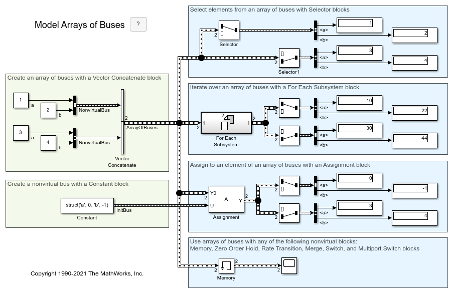
You can use an array of buses as an input signal to an Assignment block.
Assignment Block in Conditional Subsystem
If you place an Assignment block in a conditional subsystem block, a hidden signal buffer (which is equivalent to a Signal Conversion block) is inserted in many cases, and merging of signals from Assignment blocks with partial writes can cause an error.
However, if you select the Ensure outport is virtual parameter for the conditional subsystem Outport block, such cases are supported and partial writes to arrays using Assignment blocks are possible. See Ensure Output Port Is Virtual.

Examples
Limitations
The Index parameter is not tunable during simulation. If the Index Option for a dimension is set to
Index vector (dialog)orStarting index (dialog)and you specify a symbolic value, including aSimulink.Parameterobject, for the corresponding Index in the block dialog, then the instantaneous value at the start of simulation will be used throughout the simulation, and the parameter will appear as an inlined value in the generated code. See Tune and Experiment with Block Parameter Values. You can adjust the assignment index dynamically by using index ports.
Ports
Input
Output
Parameters
Block Characteristics
Data Types |
|
Direct Feedthrough |
|
Multidimensional Signals |
|
Variable-Size Signals |
|
Zero-Crossing Detection |
|


