Signal Upsampling and Interpolation Filtering
This example shows how to upsample a signal and apply a lowpass interpolation filter with interp. Upsampling by L inserts L – 1 zeros between every element of the original signal. Upsampling can create imaging artifacts. Lowpass filtering following upsampling can remove these imaging artifacts. In the time domain, lowpass filtering interpolates the zeros inserted by upsampling.
Create a discrete-time signal whose baseband spectral support is . Plot the magnitude spectrum.
f = [0 0.250 0.500 0.7500 1];
a = [1.0000 0.5000 0 0 0];

nf = 512;
b = fir2(nf-1,f,a);
Hx = fftshift(freqz(b,1,nf,"whole"));

omega = -pi:2*pi/nf:pi-2*pi/nf;
plot(omega/pi,abs(Hx))
grid
xlabel("\times\pi rad/sample")
ylabel("Magnitude")

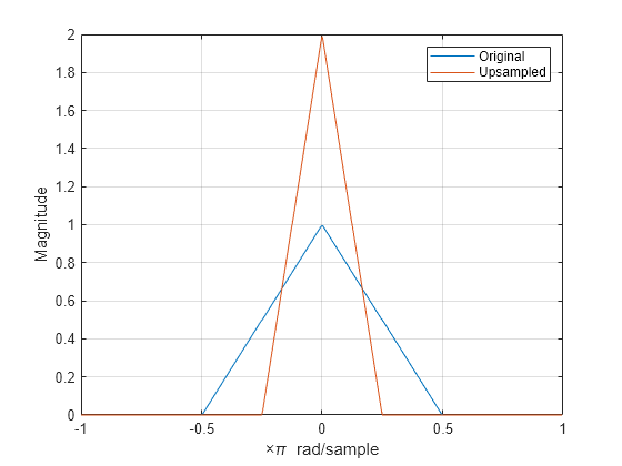
Upsample the signal and apply a lowpass filter to remove the imaging artifacts. Plot the magnitude spectrum. Upsampling still contracts the spectrum, but the imaging artifacts are removed by the lowpass filter.
y = interp(b,2);
Hy = fftshift(freqz(y,1,nf,"whole"));

hold on
plot(omega/pi,abs(Hy))
hold off
legend("Original","Upsampled")
