DVB-S2X Link Simulation with RF Impairments and Corrections for VL-SNR Frames
This example shows how to measure the bit error rate (BER) and packet error rate (PER) of a single stream Digital Video Broadcasting Satellite Second Generation extended (DVB-S2X) link that has constant coding and modulation for very low signal to noise ratio (VL-SNR) frames. The example describes the symbol timing, frame and carrier synchronization strategies in detail emphasizing on how to estimate the RF front-end impairments under severe noise conditions. The single stream signal adds RF front-end impairments and then passes the waveform through an additive white Gaussian noise (AWGN) channel.
Introduction
An increasing number of DVB-S2X terminals are being used on trains, buses, boats, and airplanes. Many applications, such as sensor networks, remote infrastructure monitoring, and emergency services, require ubiquitous coverage, and low data rates. Support for these applications was therefore included in the design of DVB-S2X, introducing VL-SNR configurations to increase the operating range to cover current and emerging applications that can benefit from operation at very low SNR. The DVB-S2X standard added nine additional modulation and coding schemes (MODCODs) in the QPSK and BPSK range. These MODCODs enable the satellite networks to deal with heavy atmospheric fading and to enable use of smaller antennas for applications in motion (land, sea, and air).
These figures show the two formats used for VL-SNR frames.
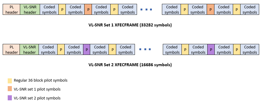
This example designs the synchronization aspects of a DVB-S2X receiver used for VL-SNR applications. The example supports all the nine MODCODs defined by the standard.
ETSI EN 302 307-2 Section 6 Table 20a, Table 20b, and Table 20c [1] summarizes the Quasi-Error-Free (QEF) performance requirement over an AWGN channel for different modulation schemes and code rates. The operating range for VL-SNR applications is considered from -2 dB to -10 dB. Because the operating range is low, the carrier, frame, and symbol timing synchronization strategies are challenging design problems.
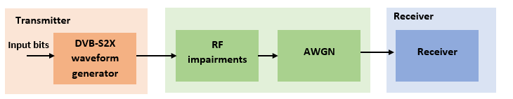
This diagram summarizes the example workflow.
Main Processing Loop
The example processes 20 physical layer (PL) frames of data with the set to 5 dB, and then computes the BER and PER. Carrier frequency offset, frequency drift, symbol timing offset, sampling clock offset, and phase noise impairments are applied to the modulated signal, and AWGN is added to the signal. ETSI EN 302 307-2 Section 4.4.4 describes the typical RF impairment ranges used under VL-SNR conditions.
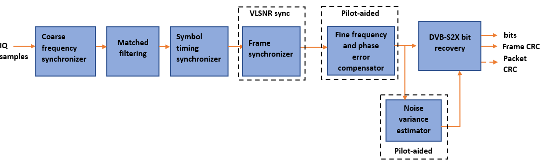
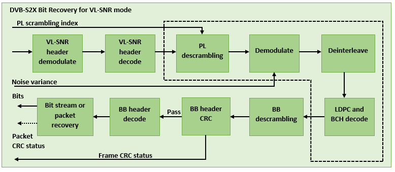
To extract PL frames, the receiver processes the distorted waveform through various timing and carrier recovery strategies. The fine frequency and carrier phase recovery algorithms are pilot-aided. To decode the data frames, the physical layer transmission parameters, such as VL-SNR set type, MODCOD, and FEC frame type are recovered from the VL-SNR header. To regenerate the input bit stream, the baseband (BB) header is decoded.
Because the DVB-S2X standard supports packetized and continuous modes of transmission, the BB frame can be either a concatenation of user packets or a stream of bits. The BB header is recovered to determine the mode of transmission. If the BB frame is a concatenation of user packets, the packet cyclic redundancy check (CRC) status of each packet is returned along with the decoded bits, and then the PER and BER are measured.
These block diagrams show the synchronization and input bit recovery workflows.
DVB-S2X Configuration
Specify the cfgDVBS2X structure to define DVB-S2X transmission configuration parameters. PLSDecimalCode 129 and 131 are the only supported formats because they are used for generating VL-SNR frames.
cfgDVBS2X.StreamFormat = "TS";
cfgDVBS2X.PLSDecimalCode = 129;
cfgDVBS2X.CanonicalMODCODName = "QPSK 2/9";
cfgDVBS2X.DFL = 14128;
cfgDVBS2X.RolloffFactor = 0.35;
cfgDVBS2X.SamplesPerSymbol = 2
cfgDVBS2X = struct with fields:
           StreamFormat: "TS"
         PLSDecimalCode: 129
    CanonicalMODCODName: "QPSK 2/9"
                    DFL: 14128
          RolloffFactor: 0.3500
       SamplesPerSymbol: 2
Simulation Parameters
The DVB-S2X standard supports flexible channel bandwidths. Use a typical channel bandwidth such as 36 MHz. The channel bandwidth can be varied from 10MHz to 72MHz. The coarse frequency synchronization algorithm implemented in this example can track carrier frequency offsets up to 20% of the input symbol rate. The symbol rate is calculated as B/(1+R), where B is the channel bandwidth, and R is the transmit filter roll-off factor. The algorithms implemented in this example can correct the sampling clock offset up to 10 ppm.
This table defines the phase noise mask (dBc/Hz) used to generate the phase noise that is applied to the transmitted signal. These noise masks are specified in ETSI TR 102 376-1 Section 4.3 [2]. The peak doppler and frequency drift supported are specified in ETSI TR 102 376-1 Section 4.4.4.
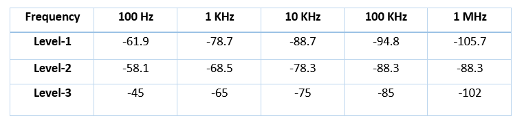
simParams.sps = cfgDVBS2X.SamplesPerSymbol;    % Samples per symbol
simParams.numFrames = 20;                      % Number of frames to be processed
simParams.chanBW = 36e6;                       % Channel bandwidth in Hertz
simParams.cfo = 3e6;                           % Carrier frequency offset in Hertz due
                                               % to oscillator instabilities
simParams.dopplerRate = 3e3;                   % Doppler rate in Hertz/sec
simParams.peakDoppler = 20e3;                  % Peak doppler shift due to receiver motion
simParams.sco = 10;                            % Sampling clock offset in parts per
                                               % million
simParams.phNoiseLevel = "Level-1";            % Phase noise level
simParams.EsNodB = 5;                          % Energy per symbol to noise ratio
Generate DVB-S2X VL-SNR Waveform Distorted with RF Impairments
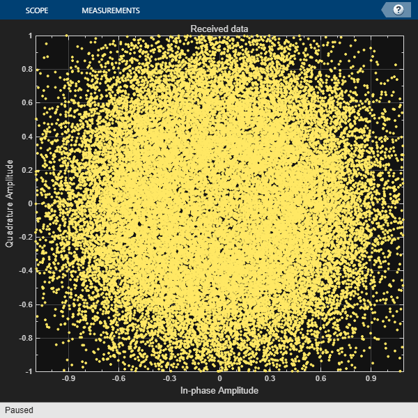
To create a DVB-S2X waveform, use the HelperDVBS2XVLSNRRxInputGenerate helper function with the simParams and cfgDVBS2X structures as inputs. The function returns the data signal, transmitted, and received waveforms, physical layer configuration parameters as a structure, and a receiver processing structure. The received waveform is impaired with carrier frequency, frequency drift, symbol timing, sampling clock offsets, and phase noise and then passed through an AWGN channel. The receiver processing parameters structure, rxParams, includes the reference pilot fields, pilot indices, counters, and buffers. Plot the constellation of the received symbols and the spectrum of the transmitted and received waveforms.
[data,txOut,rxIn,phyConfig,rxParams] = ...
    HelperDVBS2XVLSNRRxInputGenerate(cfgDVBS2X,simParams);
disp(phyConfig)
FECFrame: "normal"
ModulationScheme: "QPSK"
LDPCCodeIdentifier: "2/9"
% Received signal constellation plot
rxConst = comm.ConstellationDiagram(Title = "Received data", ...
AxesLimits = [-1 1], ...
ShowReferenceConstellation = false, ...
SamplesPerSymbol = simParams.sps);
rxConst(rxIn(1:rxParams.plFrameSize*simParams.sps))
% Transmitted and received signal spectrum visualization
Rsymb = simParams.chanBW/(1 + cfgDVBS2X.RolloffFactor);
Fsamp = Rsymb*simParams.sps;
specAn = spectrumAnalyzer(SampleRate = Fsamp, ...
ChannelNames = ["Transmitted waveform" "Received waveform"], ...
ShowLegend = true);
specAn([txOut,rxIn(1:length(txOut))]);

Configure Receiver Parameters
At the receiver, coarse frequency synchronization is performed on the received data and is then followed by matched filtering and symbol timing synchronization. The coarse frequency and symbol timing estimators are non-data aided. The coarse frequency estimation algorithm can track carrier frequency offsets up to 20% of the input symbol rate. The coarse frequency estimation, implemented as a first order frequency locked loop (FLL), reduces the frequency offset to a level that the fine frequency estimator can track. The preferred loop bandwidth for symbol timing and coarse frequency compensation depends on the setting.
When you decrease the , reduce the loop bandwidth to filter out more noise during acquisition. The number of frames required for the symbol synchronizer and coarse FLL to converge depends on the loop bandwidth setting.
Symbol timing synchronization is followed by frame synchronization and MODCOD format detection. The frame synchronization uses the VL-SNR header. Because the fine frequency and carrier phase synchronization are data-aided, the frame synchronization must detect the start of frame accurately.
The fine frequency estimation can track carrier frequency offsets up to 3.5% of the input symbol rate. The fine frequency estimation must process multiple pilot blocks for the residual carrier frequency offset to be reduced to levels acceptable for the phase estimation algorithm. The phase estimation algorithm can handle residual carrier frequency error less than 0.05% of the input symbol rate.
These settings are assigned in the rxParams structure for synchronization processing. For details on how to set these parameters for low values, see the Further Exploration section.
rxParams.carrSyncLoopBW = 1e-4;          % Coarse frequency estimator loop bandwidth
                                         % normalized by symbol rate
rxParams.symbSyncLoopBW = 1e-4;          % Symbol timing synchronizer loop bandwidth
                                         % normalized by symbol rate
rxParams.initialTimeFreqSync = 5;        % Number of frames required for coarse frequency
                                         % and symbol timing error convergence
rxParams.fineFreqLock = 4;               % Number of frames required for fine
                                         % frequency estimation
rxParams.NeedSmoothening = false;        % Smoothen the phase estimate

% Total frames used for overall synchronization
rxParams.totalSyncFrames = rxParams.initialTimeFreqSync + rxParams.fineFreqLock;

% Create coarse frequency synchronization System object by using
% HelperDVBS2XVLSNRCoarseFreqSynchronizer helper object
freqSync = HelperDVBS2XVLSNRCoarseFreqSynchronizer(SamplesPerSymbol = simParams.sps, ...
    NormalizedLoopBandwidth = rxParams.carrSyncLoopBW);

% Create symbol timing synchronization System object by using
% comm.SymbolSynchronizer object
symSync = comm.SymbolSynchronizer(TimingErrorDetector = "Gardner (non-data-aided)", ...
    NormalizedLoopBandwidth = rxParams.symbSyncLoopBW);

% Create matched filter System object by using
% comm.RaisedCosineReceiveFilter object
if simParams.sps == 2
    decFac = 1;
else
    decFac = simParams.sps/(simParams.sps/2);
end
rxFilter = comm.RaisedCosineReceiveFilter( ...
    RolloffFactor = 0.35, ...
    InputSamplesPerSymbol = simParams.sps, ...
    DecimationFactor = decFac);
b = rxFilter.coeffs;
rxFilter.Gain = sum(b.Numerator);

% Initialize error computing parameters
[numFramesLost,pktsErr,bitsErr,pktsRec] = deal(0);

% Initialize data indexing variables
stIdx = 0;
dataSize = rxParams.inputFrameSize;
plFrameSize = rxParams.plFrameSize;
isLastFrame = false;
rxParams.fineFreqCorrVal = zeros(rxParams.fineFreqLock,1);
[formatIdx,formatIdxTemp] = deal(1);
vlsnrSyncStIdx = 93;
payloadStIdx = 899;
vlSNRFrameLen = plFrameSize - vlsnrSyncStIdx + 1;
Timing and Carrier Synchronization and Data Recovery
To synchronize the received data and recover the input bit stream, process the distorted DVB-S2X waveform samples one frame at a time by following these steps.
Apply coarse frequency synchronization using a balanced quadricorrelator frequency error detector (BQ-FED) in an FLL [5].
Apply matched filtering, outputting at the rate of two samples per symbol.
Apply symbol timing synchronization using the Gardner timing error detector with an output generated at the symbol rate.
Apply frame synchronization to detect the start of frame and MODCOD format to identify the pilot positions.
Estimate and apply fine frequency offset correction.
Estimate and compensate for residual carrier frequency and phase noise.
Demodulate and decode the VL-SNR frames.
Perform CRC check on the BB header, if the check passes, recover the header parameters.
Regenerate the input stream of data or packets from BB frames.
while stIdx < length(rxIn)

    % Use one DVB-S2X PL frame for each iteration.
    endIdx = stIdx + rxParams.plFrameSize*simParams.sps;

    % In the last iteration, all the remaining samples in the received
    % waveform are considered.
    isLastFrame = endIdx > length(rxIn);
    endIdx(isLastFrame) = length(rxIn);
    rxData = rxIn(stIdx+1:endIdx);

    % After coarse frequency offset loop is converged, the FLL works with
    % previous frequency estimate.
    if rxParams.frameCount < rxParams.initialTimeFreqSync
        coarseFreqLock = false;
    else
        coarseFreqLock = true;
    end

    % Retrieve the last frame samples.
    if isLastFrame
        resSampCnt = plFrameSize*rxParams.sps - length(rxData);
        % Inadequate number of samples to fill last frame
        syncIn = [rxData; zeros(resSampCnt,1)];
    else
        syncIn = rxData;
    end

    % Apply coarse frequency offset compensation.
    [coarseFreqSyncOut,phEst] = freqSync(syncIn,coarseFreqLock);

    % Perform matched filtering and downsample the signal to 2 samples per
    % symbol.
    filtOut = rxFilter(coarseFreqSyncOut);

    % Apply symbol timing synchronization.
    symSyncOut = symSync(filtOut);

    % Apply frame synchronization and identify the MODCOD format. VL-SNR
    % sync frame is detected. PL header preceding the VL-SNR header is
    % ignored.
    if rxParams.frameCount > rxParams.initialTimeFreqSync && ~isLastFrame
        [~,rxParams.syncIndex,formatIdx] = ...
            HelperDVBS2XVLSNRFrameSync(symSyncOut,rxParams.SegLength);
        % MODCOD format identification failure verification
        formatFail = formatIdxTemp ~= rxParams.refFormat;
        if formatFail && ~isLastFrame
            % Update the counters, state variables, and buffers
            stIdx = endIdx;
            rxParams.frameCount = rxParams.frameCount + 1;
            formatIdxTemp = formatIdx;
            rxParams.cfBuffer = symSyncOut(rxParams.syncIndex:end);
            fprintf("%s\n","MODCOD format detection failed")
            continue;
        else
            fprintf("%s\n","MODCOD format detection passed")
            [setNum,phyParams] = getVLSNRParams(formatIdxTemp);
        end
    end

    % The PL frame start index lies somewhere in the middle of the data
    % being processed. From fine frequency estimation onwards, the
    % processing happens as a PL frame. A buffer is used to store symbols
    % required to fill one PL frame. PL frame is considered from
    % the start of VL-SNR header, precisely from the start of the 896 bit
    % length Walsh Hadamard (WH) sequence. 90 represents the PL header
    % length, and 2 accounts for the two zeros appended before the WH sequence.
    fineFreqIn = [rxParams.cfBuffer;...
        symSyncOut(1:vlSNRFrameLen-length(rxParams.cfBuffer))];

    % Estimate the fine frequency error by using the HelperDVBS2FineFreqEst
    % helper function.
    % Add 1 to the conditional check because the buffer used to get one PL
    % frame introduces a delay of one to the loop count.
    if (rxParams.frameCount > rxParams.initialTimeFreqSync + 1)
        % Extract the payload by removing header
        payload = fineFreqIn(payloadStIdx:end);

        % Get the correlation estimate from the regular 36 length pilot blocks.
        est1 = HelperDVBS2FineFreqEst( ...
            payload(rxParams.regPilotInd),rxParams.regNumPilotBlks, ...
            rxParams.regPilotSeq,rxParams.fineFreqState,36,rxParams.NumLags);

        % Get the correlation estimate from the VL-SNR extra pilot blocks.
        % vlSNRPilotBlk1Params contains the VL-SNR type 1 pilot block
        % length and number of blocks in one frame.
        Lp = rxParams.vlSNRPilotBlk1Params(1);
        est2 = HelperDVBS2FineFreqEst( ...
            payload(rxParams.vlSNRPilotInd1),rxParams.vlSNRPilotBlk1Params(2), ...
            rxParams.vlSNRPilotSeq1,rxParams.fineFreqState,Lp,rxParams.NumLags);

        % vlSNRPilotBlk2Params contains the VL-SNR type 2 pilot block
        % length and number of blocks in one frame.
        Lp = rxParams.vlSNRPilotBlk2Params(1);
        est3 = HelperDVBS2FineFreqEst( ...
            payload(rxParams.vlSNRPilotInd2),rxParams.vlSNRPilotBlk2Params(2), ...
            rxParams.vlSNRPilotSeq2,rxParams.fineFreqState,Lp,rxParams.NumLags);

        estVal = est1 + est2 + est3;
        % Use the correlation values calculated over pilot fields spanning over
        % multiple frames to calculate the fine frequency error estimate.
        % The estimation uses a sliding window technique.
        rxParams.fineFreqCorrVal = [rxParams.fineFreqCorrVal(2:end);estVal];
    end

    if rxParams.frameCount >= rxParams.totalSyncFrames
        fineFreqLock = true;
    else
        fineFreqLock = false;
    end

    if fineFreqLock
        freqEst = angle(sum(rxParams.fineFreqCorrVal))/(pi*(rxParams.NumLags+1));
        ind = (rxParams.frameCount-2)*plFrameSize:(rxParams.frameCount-1)*plFrameSize-1;
        phErr = exp(-1j*2*pi*freqEst*ind).';
        % 92 accounts for the PL header (90), and 2 for zeros appended before the WH
        % sequence.
        fineFreqOut = fineFreqIn(1:vlSNRFrameLen).*phErr(vlsnrSyncStIdx:end);
        % 898 accounts for the 896 length WH sequence, and 2 zeros padded to the
        % header.
        rxPilots = fineFreqOut(rxParams.pilotInd+payloadStIdx-1);
        phErrEst = HelperDVBS2PhaseEst(rxPilots,rxParams.pilotSeq, ...
            rxParams.phErrState,rxParams.IsVLSNR,setNum,rxParams.Alpha);
        if rxParams.NeedSmoothening
            phErrEst =  smoothenEstimate(phErrEst);
        end
        phaseCompOut = HelperDVBS2PhaseCompensate(fineFreqOut(payloadStIdx:end), ...
            phErrEst,rxParams.pilotInd,setNum,rxParams.IsVLSNR);
    end

    % Recover the input bit stream.
    if rxParams.frameCount >= rxParams.totalSyncFrames
        isValid = true;
        syncOut = phaseCompOut;
    else
        isValid = false;
        syncOut = [];
    end

    % Update the buffers and counters.
    rxParams.cfBuffer = symSyncOut(rxParams.syncIndex:end);

    if isValid  % Data valid signal
        % Estimate noise variance by using
        % HelperDVBS2NoiseVarEstimate helper function.
        nVar = HelperDVBS2NoiseVarEstimate(syncOut,rxParams.pilotInd, ...
            rxParams.pilotSeq,false);
        % Recover the BB frame by using HelperDVBS2XBBFrameRecover
        % helper function.
        plsDecimalCode = 129 + 2*(setNum == 2);
        headerRemoved = HelperReferenceHeaderGenerate(plsDecimalCode, formatIdx);
        [decBitsTemp, isFrameLost, pktCRC] = dvbs2xBitRecover([headerRemoved;syncOut], nVar,...
            Mode="vl-snr",...
            PLScramblingIndex=rxParams.plScramblingIndex);
        decBits = decBitsTemp{:};
        % Recover the input bit stream by using
        % HelperDVBS2StreamRecover helper function.
        if strcmpi(cfgDVBS2X.StreamFormat,"GS") && ~rxParams.UPL
            if ~isFrameLost && length(decBits) ~= dataSize
                isFrameLost = true;
            end
        else
            if ~isFrameLost && length(decBits) ~= dataSize
                isFrameLost = true;
                pktCRC = zeros(0,1,"logical");
            end
            % Compute the PER for TS or GS packetized
            % mode.
            pktsErr = pktsErr + numel(pktCRC{:}) - sum(pktCRC{:});
            pktsRec = pktsRec + numel(pktCRC{:});
        end
        if ~isFrameLost
            ts = sprintf("%s","BB header decoding passed.");
        else
            ts = sprintf("%s","BB header decoding failed.");
        end
        % Compute the number of frames lost. CRC failure of the
        % baseband header is considered a frame loss.
        numFramesLost = isFrameLost + numFramesLost;
        fprintf("%s(Number of frames lost = %1d)\n",ts,numFramesLost)
        % Compute the bits in error.
        if ~isFrameLost
            dataInd = (rxParams.frameCount-2)*dataSize+1:(rxParams.frameCount-1)*dataSize;
            errs = nnz(data(dataInd) ~= decBits);
            bitsErr = bitsErr + errs;
        end
    end

    stIdx = endIdx;
    rxParams.frameCount = rxParams.frameCount + 1;
    formatIdxTemp = formatIdx;
end
MODCOD format detection passed
MODCOD format detection passed
MODCOD format detection passed
MODCOD format detection passed
BB header decoding passed.(Number of frames lost = 0)
MODCOD format detection passed
BB header decoding passed.(Number of frames lost = 0)
MODCOD format detection passed
BB header decoding passed.(Number of frames lost = 0)
MODCOD format detection passed
BB header decoding passed.(Number of frames lost = 0)
MODCOD format detection passed
BB header decoding passed.(Number of frames lost = 0)
MODCOD format detection passed
BB header decoding passed.(Number of frames lost = 0)
MODCOD format detection passed
BB header decoding passed.(Number of frames lost = 0)
MODCOD format detection passed
BB header decoding passed.(Number of frames lost = 0)
MODCOD format detection passed
BB header decoding passed.(Number of frames lost = 0)
MODCOD format detection passed
BB header decoding passed.(Number of frames lost = 0)
MODCOD format detection passed
BB header decoding passed.(Number of frames lost = 0)
MODCOD format detection passed
BB header decoding passed.(Number of frames lost = 0)
BB header decoding passed.(Number of frames lost = 0)
Visualization and Error Logs
Plot the constellation of the synchronized data and compute the BER and PER.
% Synchronized data constellation plot
syncConst = comm.ConstellationDiagram(Title = "Synchronized data", ...
AxesLimits = [-1.7 1.7], ...
ShowReferenceConstellation = false);
syncConst(syncOut)

pause(0.5)
% Error metrics display
% For GS continuous streams
if strcmpi(cfgDVBS2X.StreamFormat,"GS") && ~rxParams.UPL
    if (simParams.numFrames-rxParams.totalSyncFrames == numFramesLost)
        fprintf("All frames are lost. No bits are retrieved from BB frames.")
    else
        numFramesRec = simParams.numFrames - rxParams.totalSyncFrames - numFramesLost;
        ber = bitsErr/(numFramesRec*dataSize);
        fprintf("BER           : %1.2e\n",ber)
    end
else
    % For GS and TS packetized streams
    if pktsRec == 0
        fprintf("All frames are lost. No packets are retrieved from BB frames.")
    else
        if strcmpi(cfgDVBS2X.StreamFormat,"TS")
            pktLen = 1504;
        else
            pktLen = cfgDVBS2X.UPL;      % UP length including sync byte
        end
        ber = bitsErr/(pktsRec*pktLen);
        per = pktsErr/pktsRec;
        fprintf("PER: %1.2e\n",per)
        fprintf("BER: %1.2e\n",ber)
    end
end
PER: 0.00e+00
BER: 0.00e+00
Further Exploration
The operating range of the VL-SNR mode being very low requires the normalized loop bandwidth of the symbol synchronizer and coarse FLL to be very small for accurate estimation. Set these parameters using the rxParams.symbSyncLoopBW and rxParams.carrSyncLoopBW.
Configure Coarse Carrier Synchronization Parameters
Initialize HelperDVBS2XVLSNRCoarseFreqSynchronizer System object with rxParams.carrSyncLoopBW set as 2e-5 and then run the simulation.
When you set the PLSDecimalCode property to 129, set the rxParams.initialTimeFreqSync property to 15. When you set the PLSDecimalCode property to 131, set the rxParams.coarseFreqLock property to 30. Set simParams.EsNodB to the lowest for the chosen modulation scheme from ETSI EN 302 307-1 Section 6 [1].
Replace the code in the coarse frequency synchronization section with these lines of code. Run the simulation for different carrier frequency offset (CFO) values. After coarse frequency compensation, view the plot and the residual CFO value (resCoarseCFO) over each frame to observe the performance of the coarse frequency estimation algorithm. Ideally, the coarse frequency compensation reduces the error to 2% of the symbol rate. If the residual CFO error is not reduced to less than 2% of the symbol rate, try decreasing the loop bandwidth and increasing the rxParams.initialTimeFreqSync. The coarse frequency is a first order FLL, and it can only detect the static carrier frequency offset. It cannot track Doppler rate changes.
% [coarseFreqSyncOut,phEst] = freqSync(syncIn,false);
% Frequency offset estimate normalized by symbol rate
% freqOffEst = diff(phEst(1:simParams.sps:end))/(2*pi);
% plot(freqOffEst)
% Rsym = simParams.chanBW/(1+cfgDVBS2X.RolloffFactor);
% actFreqOff = (simParams.cfo + simParams.peakDoppler)/Rsym;
% resCoarseCFO = abs(actFreqOff-freqOffEst(end));
When the residual carrier frequency offset value (resCoarseCFO) is reduced to approximately 0.02, set the rxParams.frameCount as the rxParams.initialTimeFreqSync value.
Configure Symbol Timing Synchronization Parameters
Try running the simulation using the symbol timing synchronizer configured with a normalized loop bandwidth of 1e-4. To achieve convergence of the timing loop, the ratio rxParams.symbSyncLoopBW/simParams.sps must be greater than 1e-5. If the symbol timing loop doesn't converge, try decreasing the rxParams.symbSyncLoopBW.
Configure Frame Synchronization Parameters
Proper frame synchronization depends on the segment length, rxParams.SegLength, which is used to divide the reference VL-SNR header symbols into smaller segments to perform segment coherent correlation. rxParams.SegLength depends on the residual CFO that is present after coarse frequency synchronization and must be less than round(3/(8*resCoarseCFO)). Prefer using a value that is an integer multiple of 896 (length of VL-SNR WH sequence). If CFO is absent, perform correlation using rxParams.SegLength as 896.
Configure Fine Frequency Synchronization Parameters
When you set the PLSDecimalCode property to 129, set the rxParams.fineFreqLock property to 10. When you set the PLSDecimalCode property to 131, set the rxParams.coarseFreqLock property to 20. Set simParams.EsNodB to the lowest for the chosen modulation scheme from ETSI EN 302 307-1 Section 6 [1].
Replace the code in the fine frequency error estimation section with this code. Fine frequency estimator tracks the Doppler rate changes. To estimate the residual CFO error, include the sinusoidal variation of the Doppler shift included in the actFreqOff estimate. For an easy workaround, do not introduce Doppler rate in impairment. Instead, add only static CFO and analyze the number of frames required to generate an accurate estimate. Typically, those number of frames are sufficient to estimate CFO changes due to Doppler rate. As the Doppler rate changes are handled by the fine frequency estimator, 2*simParams.peakDoppler must be less than the estimation range of the fine frequency estimator. The estimation range depends on the rxParams.NumLags parameter and the normalized CFO that can be estimated is given by 1/(rxParams.NumLags+1). To increase the estimation range, try reducing the rxParams.NumLags. You might need more pilot blocks because the estimation accuracy drops.
% fineFreqEst = angle(sum(rxParams.fineFreqCorrVal))/(pi*(rxParams.NumLags+1));
% resFineCFO = abs(actFreqOff-freqOffEst(end)-fineFreqEst);
Repeat the simulation process and observe the residual CFO value (resFineCFO) over each frame. If the fine frequency estimator does not reduce the residual carrier frequency error to approximately 0.03% of the symbol rate, try increasing the rxParams.fineFreqLock property value.
When the residual CFO value (resFineCFO) is reduced to approximately 0.0003, update rxParams.totalSyncFrames based on rxParams.initialTimeFreqSyncrxParams and rxParams.fineFreqLock values.
Configure Phase Synchronization Parameters
HelperDVBS2PhaseEstimate estimates the residual CFO and phase error appropriately up to -8 dB of . For less than -8 dB, set rxParams.Alpha to less than 0.5 if data that passed through HelperDVBS2PhaseEstimate has only phase error. If the data has residual CFO along with phase error, keep rxParams.Alpha as 1 and set rxParams.NeedSmoothening as true. Smoothening improves the phaseEst obtained from HelperDVBS2PhaseEstimate.
After refining the synchronization parameters set in the rxParams structure, perform the BER simulation for the updated configuration.
Supporting Files
The example uses these helper functions:
HelperDVBS2XVLSNRRxInputGenerate.m: Generate DVB-S2X waveform samples distorted with RF impairments and structure of parameters for receiver processingHelperDVBS2PhaseNoise.m: Generate phase noise samples for different DVB-S2X phase noise masks and apply it to the input signalHelperDopplerShift.m: Generate sinusoidal varying Doppler shift and apply it to input signalHelperDVBS2XVLSNRCoarseFreqSynchronizer.m: Perform coarse frequency offset estimation and correctionHelperDVBS2XVLSNRFrameSync.m: Perform frame synchronization and detect start of VL-SNR header and MODCOD identificationHelperDVBS2FineFreqEst.m: Estimate fine frequency offsetHelperDVBS2PhaseEst.m: Estimate carrier phase offsetHelperDVBS2PhaseCompensate.m: Perform carrier phase compensationHelperDVBS2NoiseVarEstimate.m: Estimate noise variance of received dataHelperReferenceHeaderGenerate.m: Generate a reference PLHeader and VL-SNR header using the decoded parameters
References
ETSI Standard EN 302 307-2 V1.1.1(2015-11). Digital Video Broadcasting (DVB); Second Generation Framing Structure, Channel Coding and Modulation Systems for Broadcasting, Interactive Services, News Gathering and other Broadband Satellite Applications; Part 2: DVB-S2 extensions (DVB-S2X).
ETSI Standard TR 102 376-2 V1.2.1(2015-11). Digital Video Broadcasting (DVB); Implementation Guidelines for the Second Generation System for Broadcasting, Interactive Services, News Gathering and other Broadband Satellite Applications; Part 2: S2 extensions (DVB-S2X).
ETSI Standard TR 102 376-1 V1.2.1(2015-11). Digital Video Broadcasting (DVB); Implementation Guidelines for the Second Generation System for Broadcasting, Interactive Services, News Gathering and other Broadband Satellite Applications (DVB-S2).
Mengali, Umberto, and Aldo N.D'Andrea. Synchronization Techniques for Digital Receivers. New York: Plenum Press,1997.
D’Andrea, A. N., and U. Mengali. “Design of Quadricorrelators for Automatic Frequency Control Systems.” IEEE Transactions on Communications, vol. 41, no. 6, June 1993, pp. 988–97.
Casini, E., et al. “DVB-S2 Modem Algorithms Design and Performance over Typical Satellite Channels.” International Journal of Satellite Communications and Networking, vol. 22, no. 3, May 2004, pp. 281–318.
Michael Rice, Digital Communications: A Discrete-Time Approach. New York: Prentice Hall, 2008.
Local Functions
function [setNum,phyParams] = getVLSNRParams(formatIdx)

tableVLSNR = [4 64800 2/9 0; ...
    2 32400 1/5 0; ...
    2 32400 11/45 0; ...
    2 32400 1/3 0; ...
    2 16200 1/5 1; ...
    2 16200 11/45 1; ...
    2 16200 1/5 0; ...
    2 16200 4/15 0; ...
    2 16200 1/3 0];

params = tableVLSNR(formatIdx,:);
phyParams.ModOrder = params(1);
phyParams.FECFrameLen = params(2);
phyParams.CodeRate = params(3);
[n, d] = rat(phyParams.CodeRate);
phyParams.CodeIDF = [sprintf('%0.0f',n) '/' sprintf('%0.0f',d)];
phyParams.HasPilots = true;
phyParams.HasSpread = params(4);

if formatIdx > 6
    setNum = 2;
else
    setNum = 1;
end
end
% Smoothen the phase estimate using moving average filter
function newEst = smoothenEstimate(est)
errDiff = diff(est(2:end));
thres = -2*sign(mean(errDiff));
width = 5;
if thres > 0
   index = find(errDiff > thres);
else
  index = find(errDiff < thres);
end
if ~isempty(index)
    for k = 1:length(index)
        est(index(k)+2:end) = est(index(k)+2:end)-sign(thres)*2*pi;
    end
end
temp = est(2:end);
n = length(temp);
c = filter(ones(width,1)/width,1,temp);
cbegin = cumsum(temp(1:width-2));
cbegin = cbegin(1:2:end)./(1:2:(width-2))';
cend = cumsum(temp(n:-1:n-width+3));
cend = cend(end:-2:1)./(width-2:-2:1)';
c = [cbegin;c(width:end);cend];
newEst = [est(1);c];
end