DVB-S2 Link Simulation with RF Impairments and Corrections
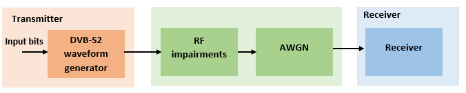
This example shows how to measure the bit error rate (BER) and packet error rate (PER) of a single stream Digital Video Broadcasting Satellite Second Generation (DVB-S2) link that has constant coding and modulation. The example describes the symbol timing and carrier synchronization strategies in detail, emphasizing how to estimate the RF front-end impairments under heavy noise conditions. The single stream signal adds RF front-end impairments and then passes the waveform through an additive white Gaussian noise (AWGN) channel.
Introduction
DVB-S2 receivers are subjected to large carrier frequency errors in the order of 20% of the input symbol rate and substantial phase noise. The use of powerful forward error correction (FEC) mechanisms, such as Bose–Chaudhuri–Hocquenghem (BCH) and low density parity check (LDPC) codes, caused the DVB-S2 system to work at very low energy per symbol to noise power spectral density ratio () values, close to the Shannon limit.
ETSI EN 302 307-1 Section 6 Table 13 [1] summarizes the Quasi-Error-Free (QEF) performance requirement over an AWGN channel for different modulation schemes and code rates. The operating range for different transmission modes can be considered as +2 or -2 dB from the point where QEF performance is observed. Because the operating range is low, carrier and symbol timing synchronization strategies are challenging design problems.
This diagram summarizes the example workflow.
Main Processing Loop
The example processes 50 physical layer (PL) frames of data with the set to 9.1 dB, and then computes the BER and PER. Carrier frequency offset, sampling clock offset, and phase noise impairments are applied to the modulated signal, and AWGN is added to the signal.
At the receiver, after matched filtering, timing and carrier recovery operations are run to recover the transmitted data. To extract PL frames, the distorted waveform is processed through various timing and carrier recovery strategies. The carrier recovery algorithms are pilot-aided. To decode the data frames, the physical layer transmission parameters such as modulation scheme, code rate, and FEC frame type, are recovered from the PL header. To regenerate the input bit stream, the baseband (BB) header is decoded.
Because the DVB-S2 standard supports packetized and continuous modes of transmission, the BB frame can be either a concatenation of user packets or a stream of bits. The BB header is recovered to determine the mode of transmission. If the BB frame is a concatenation of user packets, the packet cyclic redundancy check (CRC) status of each packet is returned along with the decoded bits, and then the PER and BER are measured.
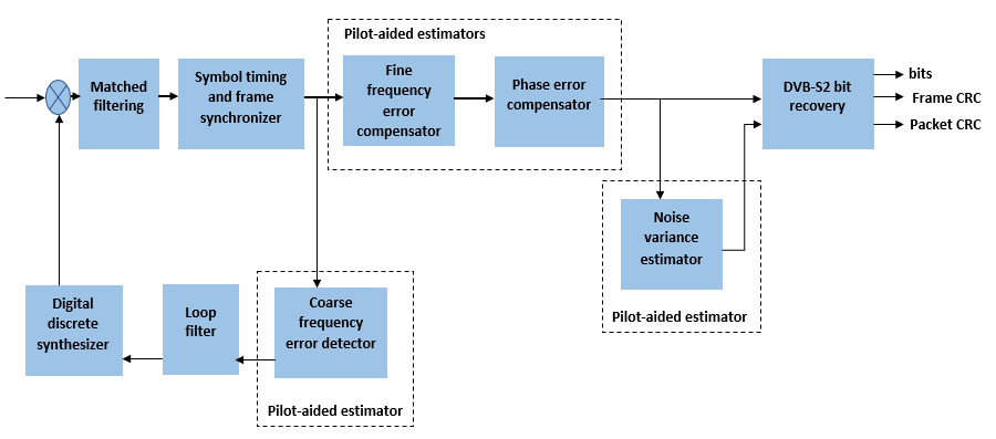
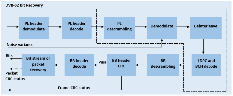
These block diagrams show the synchronization and input bit recovery workflows.
DVB-S2 Configuration in Pilot-Aided Mode
Specify the cfgDVBS2 structure to define DVB-S2 transmission configuration parameters. For details on setting the configuration parameters, see dvbs2WaveformGenerator System object™.
cfgDVBS2.StreamFormat ="TS"; cfgDVBS2.FECFrame =
"normal"; cfgDVBS2.MODCOD = 18; % 16APSK 2/3 cfgDVBS2.DFL = getDFL(cfgDVBS2.MODCOD,cfgDVBS2.FECFrame); cfgDVBS2.SamplesPerSymbol = 2; cfgDVBS2.RolloffFactor = 0.35
cfgDVBS2 = struct with fields:
        StreamFormat: "TS"
            FECFrame: "normal"
              MODCOD: 18
                 DFL: 42960
    SamplesPerSymbol: 2
       RolloffFactor: 0.3500
Simulation Parameters
The DVB-S2 standard supports flexible channel bandwidths. Use a typical channel bandwidth such as 36 MHz. The channel bandwidth can be varied. The coarse frequency synchronization algorithm implemented in this example can track carrier frequency offsets up to 20% of the input symbol rate. The symbol rate is calculated as B/(1+R), where B is the channel bandwidth, and R is the transmit filter roll-off factor. The algorithms implemented in this example can correct the sampling clock offset up to 10 ppm.
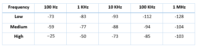
simParams.numFrames = 50; % Number of frames to be processed simParams.chanBW = 36e6; % Channel bandwidth in Hertz simParams.hasCFO = true; % Enable carrier frequency offset simParams.cfo = 3e6; % Carrier frequency offset in Hertz simParams.hasSCO = true; % Enable sampling clock offset simParams.sco = 5; % Sampling clock offset in parts % per million simParams.hasPN = true; % Enable phase noise simParams.phNoiseLevel ="Low"; % Phase noise level provided as % "Low", "Medium", or "High" simParams.EsNodB = 9.1; % Energy per symbol to noise ratio % in decibels
This table defines the phase noise mask (dBc/Hz) used to generate the phase noise applied to the transmitted signal.
Generate DVB-S2 Waveform Distorted with RF Impairments
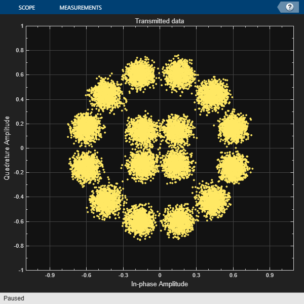
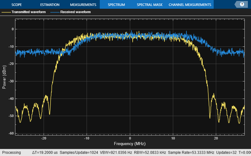
To create a DVB-S2 waveform, use the HelperDVBS2RxInputGenerate helper function with the simParams and cfgDVBS2 structures as inputs. The function returns the data signal, transmitted and received waveforms, and a receiver processing structure. The received waveform is impaired with carrier frequency, timing phase offsets, and phase noise and then passed through an AWGN channel. The receiver processing parameters structure, rxParams, includes the reference pilot fields, pilot indices, counters, and buffers. Plot the constellation of the transmitted symbols and the spectrum of the transmitted and received waveforms.
[data,txOut,rxIn,rxParams,info] = HelperDVBS2RxInputGenerate(cfgDVBS2,simParams);
disp(info)
      ModulationScheme: "16APSK"
    LDPCCodeIdentifier: "2/3"
sps = cfgDVBS2.SamplesPerSymbol;
% Transmitted and received signal spectrum visualization
Rsymb = simParams.chanBW/(1 + cfgDVBS2.RolloffFactor);
Fsamp = Rsymb*sps;
fprintf('Symbol rate in Hz = %f\n',Rsymb)
Symbol rate in Hz = 26666666.666667
% Transmitted signal constellation plot
txConst = comm.ConstellationDiagram(Title = "Transmitted data", ...
AxesLimits = [-1 1], ...
ShowReferenceConstellation = false, ...
SamplesPerSymbol = sps);
txConst(txOut(1:rxParams.plFrameSize*sps))
% Spectrum
specAn = spectrumAnalyzer(SampleRate = Fsamp, ...
ChannelNames = ["Transmitted waveform" "Received waveform"], ...
ShowLegend = true);
specAn([txOut(1:rxParams.plFrameSize*sps), rxIn(1:rxParams.plFrameSize*sps)]);
Configure Receiver Parameters
At the receiver, symbol timing synchronization is performed on the received data and is then followed by frame synchronization. The receiver algorithms include coarse and fine frequency impairment correction algorithms.
Symbol Timing Synchronization Parameters
The Gardner algorithm performs symbol timing synchronization. The preferred loop bandwidth for this synchronization depends on the setting. When you decrease , you can reduce the loop bandwidth to filter out more noise during acquisition.
rxParams.symbSyncLoopBW = 1e-4;                             % Symbol timing synchronizer loop bandwidth
                                                            % normalized by symbol rate
rxParams.symbSyncLock  = ceil(1e5/rxParams.plFrameSize);    % Number of frames required for symbol
                                                            % timing error convergence
Frame Synchronization Parameters
Frame synchronization supports two options: using the PL header alone or using both the PL header and Pilots. The value of affects frame synchronization accuracy. When detecting QPSK-modulated frames at values below 3 dB, use pilots along with PL header to improve frame detection.
rxParams.frameSyncUsePilots = cfgDVBS2.MODCOD < 6;
Carrier Synchronization Parameters
The carrier frequency estimation algorithm can track carrier frequency offsets up to 20% of the input symbol rate. The coarse frequency estimation, implemented as a frequency locked loop (FLL), reduces the frequency offset to a level that the fine frequency estimator can track.
The fine frequency estimation can track carrier frequency offsets up to 4% of the input symbol rate. The fine frequency estimation must process multiple pilot blocks for the residual carrier frequency offset to be reduced to levels acceptable for the phase estimation algorithm. The phase estimation algorithm can handle residual carrier frequency errors less than 0.02% of the input symbol rate. Fine phase compensation is only required for APSK modulation schemes in the presence of significant phase noise.
The preferred loop bandwidth for carrier synchronization depends on the setting. When you decrease , you can reduce the loop bandwidth to filter out more noise during acquisition.
These settings are assigned in the rxParams structure for synchronization processing. For details on how to set these parameters for low values, see the Further Exploration section.
rxParams.carrSyncLoopBW = 1e-3;                             % Coarse frequency estimator loop bandwidth
                                                            % normalized by symbol rate
rxParams.hasFinePhaseCompensation = false;                  % Flag to indicate whether fine phase
                                                            % compensation is used
rxParams.finePhaseSyncLoopBW = 3.5e-4;                      % Fine phase compensation loop bandwidth
                                                            % normalized by symbol rate
Initialize Receiver Variables
% Initialize error computing and data indexing parameters
[numFramesLost,pktsErr,bitsErr,pktsRec,dataStInd,stIdx] = deal(0);

% Variables for storing symbol synchronization output length, estimated coarse
% frequency offset, average coarse frequency offset, and
% starting index for every PL frame
[symSyncOutLen,cCFOEst,cCFOEstMean,syncIndex] = deal([]);

% Boolean variable that indicates whether the simulation has reached the last frame,
% and whether coarse frequency offset tracking has converged.
[isLastFrame,isCoarseFreqLocked] = deal(false);

% Counter to track the number of PL frames used for fine frequency
% offset estimation
numFreqEst = 0;

dataSize = rxParams.inputFrameSize;
plFrameSize = rxParams.plFrameSize;

% Initialize FSM variables
% Use the variables to denote current state of receiver
% STR - Symbol Timing Recovery, FS - Frame Synchronization,
% CFL - Coarse Frequency Loop, FFS - Fine Frequency Synchronization,
% PS  - Phase Synchronization, FPS - Fine Phase Synchronization
% PLR - PL Frame Recovery
stateVal = num2cell([1 2 3 4 5 6 7]);
[STR, FS, CFL, FFS, PS, FPS, PLR] = stateVal{:};
state = STR;
activeState = [true false false false false false false]';
Initialize Receiver Objects
Use pilots for frame synchronization only for QPSK PL frames operating under values below 3 dB. You can configure the number of pilot blocks, but ensure that you do not exceed half of the maximum limit per PL frame.For normal FEC frames, it is 8 and for short FEC frames, it is 2.
% Create symbol timing and coarse frequency synchronization System object
% by using HelperDVBS2Synchronizer helper object
timeFreqSync = HelperDVBS2Synchronizer( ...
    CarrSyncLoopBW = rxParams.carrSyncLoopBW, ...
    SymbSyncLoopBW = rxParams.symbSyncLoopBW, ...
    SamplesPerSymbol = sps, ...
    DataFrameSize = rxParams.xFecFrameSize);

% Create frame synchronization System object by using
% HelperDVBS2FrameSynchronizer helper object
if strcmp(cfgDVBS2.FECFrame,"normal")
    numPilotBlks = 8;
else
    numPilotBlks = 2;
end
frameSync = HelperDVBS2FrameSynchronizer( ...
    UsePilots = rxParams.frameSyncUsePilots, ...
    PLFrameLength = rxParams.plFrameSize, ...
    NumOfPilotBlocks = numPilotBlks);

% Create fine phase compensation System object by using
% HelperDVBS2FinePhaseCompensator helper object. Fine phase
% compensation is only required for 16 and 32 APSK modulated frames
if cfgDVBS2.MODCOD >= 18 && rxParams.hasFinePhaseCompensation
    finePhaseSync = HelperDVBS2FinePhaseCompensator( ...
        DataFrameSize = rxParams.xFecFrameSize, ...
        NormalizedLoopBandwidth = rxParams.finePhaseSyncLoopBW);
end
% For carrSyncLoopBW of 1e-4, 4e4 pilots are required for FLL convergence. Based
% on chosen carrSyncLoopBW and number of pilots in a frame, the minimum
% number of frames, calculate the number of frames required for
% FLL convergence.
coarseCFOEstMinFrames = floor(4/(rxParams.carrSyncLoopBW*length(rxParams.pilotInd)));
Timing and Carrier Synchronization and Data Recovery
To synchronize the received data and recover the input bit stream, the distorted DVB-S2 waveform samples are processed one frame at a time by following these steps.
Apply matched filtering, outputting at the rate of two samples per symbol.
Apply symbol timing synchronization using the Gardner timing error detector with an output generated at the symbol rate. The Gardner TED is not data-aided, so it is performed before carrier synchronization.
Apply frame synchronization to detect the start of frame and to identify the pilot positions.
Estimate and apply coarse frequency offset correction.
Estimate and apply fine frequency offset correction.
Estimate and compensate for residual carrier frequency and phase noise.
Decode the PL header and compute the transmission parameters.
Demodulate and decode the PL frames.
Perform CRC check on the BB header, if the check passes, recover the header parameters.
Regenerate the input stream of data or packets from BB frames.
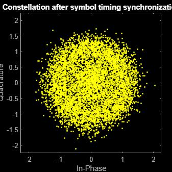
fprintf('\nPerforming symbol timing synchronization ...\n');Performing symbol timing synchronization ...
while stIdx < length(rxIn)

    % Use one DVB-S2 PL frame for each iteration.
    endIdx = stIdx + rxParams.plFrameSize*sps;

    % In the last iteration, all the remaining samples in the received
    % waveform are considered.
    isLastFrame = endIdx > length(rxIn);

    if ~isLastFrame
        rxData = rxIn(stIdx+1:endIdx);
Symbol Timing and Coarse Carrier Frequency Synchronization
        [coarseFreqSyncOut,phEst] = timeFreqSync(rxData,syncIndex,isCoarseFreqLocked);
        coarseCFOEst = diff(phEst(1:sps:end)/(2*pi));
        cCFOEst = [cCFOEst;coarseCFOEst];
Finite State Machine Transition Logic
Transition between synchronization stages based on the convergence logic of each stage, continuing until data decoding.
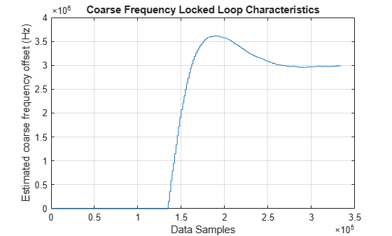
        switch state

            case STR
                symSyncOutLen = [symSyncOutLen;length(coarseFreqSyncOut)];
                if any(abs(diff(symSyncOutLen(1:rxParams.frameCount-1))) > 5)
                    error("Symbol timing synchronization failed. The loop will not " + ...
                        "converge. No frame will be recovered. Update the symbSyncLoopBW " + ...
                        "parameter according to the EsNo setting for proper loop convergence.");
                end
                if rxParams.frameCount >= rxParams.symbSyncLock
                    state = FS;
                    figure;
                    scatterplot(coarseFreqSyncOut);
                    title("Constellation after symbol timing synchronization");
                    fprintf("\nPerforming frame synchronization ...\n");
                end
            case FS
                activeState(FS) = true;
                if ~isempty(syncIndex)
                    state = CFL;
                    fprintf("\nPerforming coarse frequency synchronization ...\n");
                end
            case CFL
                activeState(CFL) = true;
                cCFOEstMean=[cCFOEstMean;mean(coarseCFOEst)]; %#ok<*AGROW>
                % Check for FLL convergence based on estimated coarse frequency
                % offset values across frames
                if length(cCFOEstMean) > coarseCFOEstMinFrames
                    diffVal = diff(abs(cCFOEstMean));
                    if all(abs(diffVal(end-2:end)) < 1e-2)
                        isCoarseFreqLocked = true;
                        state = FFS;
                        figure;
                        plot(cCFOEst*Rsymb)
                        grid on
                        ylabel("Estimated coarse frequency offset (Hz)");
                        xlabel("Data Samples")
                        title("Coarse Frequency Locked Loop Characteristics")
                        fprintf("\nPerforming fine frequency synchronization ...\n");
                    elseif rxParams.frameCount == simParams.numFrames
                        fprintf("%s\n",["Coarse frequency error estimation has either failed or it did not meet " ...
                            "convergence criteria. Try analyzing the coarse FLL characteristics from the displayed figure." ...
                            "If the CFO estimation (FLL tracking) across samples looks noisy but trends towards the correct estimation, "  ...
                            "try reducing carrSyncLoopBW and increasing coarseCFOEstMinFrames. Ensure that simParams.numFrames provides " + ...
                            "enough frames for processing. If the CFO estimation across samples is incorrect, examine syncIndex output. " + ...
                            "Since FLL uses pilots, syncIndex must be accurate for proper estimation"]);
                    end
                end
            case FFS
                activeState(FFS) = true;
                if rxParams.fineFreqCorrVal ~= 0
                    rxParams.fineFreqEstTemp(1:end-1) = rxParams.fineFreqEstTemp(2:end);
                    rxParams.fineFreqEstTemp(end) = freqEst;
                    numFreqEst = numFreqEst+1;
                end
                % Check whether the normalized fine frequency offset estimation
                % has converged to within an order of 1e–5.
                if numFreqEst>=5
                    cg = abs(diff(rxParams.fineFreqEstTemp(end-numFreqEst+1:end)));
                    if all(cg(end-2:end) < 1e-5)
                        state = PS;
                        activeState(FFS) = false;
                        fprintf("Estimated carrier frequency offset in Hz = %f\n",(coarseCFOEst(end)+freqEst).*Rsymb);
                        fprintf("\nPerforming phase synchronization ...\n");
                    elseif rxParams.frameCount == simParams.numFrames
                        fprintf("%s\n","Fine frequency error estimation has either failed or it did not meet " + ...
                            "convergence criteria. Analyze rxParams.fineFreqEstTemp to check whether the value " + ...
                            "of (coarseCFOEst(end) + freqEst) * Rsymb is approaching the actual CFO. If the " + ...
                            "estimation is trending in the right direction but the simulation has reached the final frame, " + ...
                            "increase simParams.numFrames to allow more frames for convergence. If the estimation " + ...
                            "appears incorrect, examine the coarse FLL estimation. After coarse correction, the residual " + ...
                            "normalized CFO should be less than 2% of the symbol rate.");
                    end
                end
            case PS
                activeState(PS) = true;
                if rxParams.prevPhaseEst ~= 0
                    if rxParams.hasFinePhaseCompensation && cfgDVBS2.MODCOD >= 18
                        state = FPS;
                    else
                        state = PLR;
                        rxParams.totalSyncFrames = rxParams.frameCount;
                        fprintf("\nPerforming PL frame demodulation and decoding  ...\n");
                    end
                end
            case FPS
                activeState(FPS) = true;
                state = PLR;
                rxParams.totalSyncFrames = rxParams.frameCount;
                fprintf("\nPerforming PL frame demodulation and decoding  ...\n");
            case PLR
                activeState(PLR) = true;
        end
        if ~isempty(rxParams.cfBuffer)
            fineFreqIn = [rxParams.cfBuffer; coarseFreqSyncOut(1:rxParams.plFrameSize-length(rxParams.cfBuffer))];
        end
        if ~isempty(syncIndex)
            rxParams.cfBuffer = coarseFreqSyncOut(syncIndex:end);
        end
Frame Synchronization
        if activeState(FS)
            syncIndex = frameSync(coarseFreqSyncOut);
        end
Fine Frequency Error Estimation
        if activeState(FFS)
            rxParams.fineFreqCorrVal = HelperDVBS2FineFreqEst( ...
                fineFreqIn(rxParams.pilotInd),rxParams.numPilots, ...
                rxParams.refPilots,rxParams.fineFreqCorrVal);
            % Normalize the frequency estimate by the input symbol rate
            % freqEst = angle(R)/(pi*(N+1)), where N (18) is the number of elements
            % used to compute the mean of auto correlation (R) in
            % HelperDVBS2FineFreqEst.
            freqEst = angle(rxParams.fineFreqCorrVal)/(pi*(19));
        end
Phase Compensation
        if activeState(PS)
            % Generate the symbol indices using frameCount and plFrameSize.
            % Subtract 2 from the rxParams.frameCount because the buffer used to get one
            % PL frame introduces a delay of one to the count.
            ind = (rxParams.frameCount-2)*plFrameSize:(rxParams.frameCount-1)*plFrameSize-1;
            phErr = exp(-1j*2*pi*freqEst*ind);
            fineFreqOut = fineFreqIn.*phErr(:);
            % Estimate the phase error estimation by using the HelperDVBS2PhaseEst
            % helper function.
            [phEstRes,prevPhaseEstTemp] = HelperDVBS2PhaseEst( ...
                fineFreqOut,rxParams.refPilots,rxParams.prevPhaseEst,rxParams.pilotInd);
            if rxParams.prevPhaseEst ~= 0
                coarsePhaseCompOut = HelperDVBS2PhaseCompensate(rxParams.ffBuffer, ...
                    rxParams.pilotEst,rxParams.pilotInd,phEstRes(2));
            end
            rxParams.ffBuffer = fineFreqOut;
            rxParams.pilotEst = phEstRes;

            if ~(cfgDVBS2.MODCOD >= 18 && rxParams.hasFinePhaseCompensation) && rxParams.prevPhaseEst ~= 0
                phaseCompOut = coarsePhaseCompOut;
            end
            rxParams.prevPhaseEst = prevPhaseEstTemp;
        end
        if activeState(FPS)
            phaseCompOut = finePhaseSync(coarsePhaseCompOut);
        end
PL Header Recovery
        if activeState(PLR)  % Data valid signal
            % Decode the PL header by using the dvbsPLHeaderRecover
            % function
            rxPLHeader = phaseCompOut(1:90);
            phyParams = dvbsPLHeaderRecover(rxPLHeader,Mode="DVB-S2/S2X regular");
            M = phyParams.ModulationOrder;
            if M == 0
                R = [];
            else
                R = eval(phyParams.LDPCCodeIdentifier);
            end
            fecFrame = phyParams.FECFrameLength;
            pilotStat = phyParams.HasPilots;
            xFECFrameLen = fecFrame/log2(M);
            % Validate the decoded PL header.
            if M ~= rxParams.modOrder || R ~= rxParams.codeRate || ...
                    fecFrame ~= rxParams.cwLen || ~pilotStat
                fprintf("%s\n","PL header decoding failed")
PL Data Frame Recovery
            else % Demodulation and decoding
                rxFrame = phaseCompOut(1:plFrameSize);
                % Estimate noise variance by using
                % HelperDVBS2NoiseVarEstimate helper function.
                nVar = HelperDVBS2NoiseVarEstimate(rxFrame,rxParams.pilotInd,...
                    rxParams.refPilots,false);
                % Recover the input bit stream by using
                % dvbs2BitRecover function
                [decBitsTemp, isFrameLost, pktCRC]  = dvbs2BitRecover(rxFrame,nVar);
                decBits = decBitsTemp{:};

                if ~isFrameLost && length(decBits) ~= dataSize
                    isFrameLost = true;
                end
                if ~isFrameLost && ~(strcmpi(cfgDVBS2.StreamFormat,"GS") && ~rxParams.UPL)
                    % Compute the packet error rate for TS or GS packetized
                    % mode.
                    pktsErr = pktsErr + numel(pktCRC{:}) - sum(pktCRC{:});
                    pktsRec = pktsRec + numel(pktCRC{:});
                end
                if ~isFrameLost
                    ts = sprintf("%s","BB header decoding passed.");
                else
                    ts = sprintf("%s","BB header decoding failed.");
                end
                % Compute the number of frames lost. CRC failure of baseband header
                % is considered a frame loss.
                numFramesLost = isFrameLost + numFramesLost;
                fprintf("%s(Frame index = %1d, Number of frames lost = %1d)\n",ts,rxParams.frameCount,numFramesLost);
                % Compute the bits in error.
                bitInd = (dataStInd-2)*dataSize+1:(dataStInd-1)*dataSize;
                if isLastFrame && ~isFrameLost
                    bitsErr = bitsErr + sum(data(bitInd) ~= decBits);
                else
                    if ~isFrameLost
                        bitsErr = bitsErr + sum(data(bitInd) ~= decBits);
                    end
                end
            end
        end
    end
    dataStInd = dataStInd + 1;
    stIdx = endIdx;
    rxParams.frameCount = rxParams.frameCount + 1;
end
Performing frame synchronization ...
Performing coarse frequency synchronization ...
Performing fine frequency synchronization ...
Estimated carrier frequency offset in Hz = 3003001.733289
Performing phase synchronization ...
Performing PL frame demodulation and decoding ...
BB header decoding passed.(Frame index = 32, Number of frames lost = 0)
BB header decoding passed.(Frame index = 33, Number of frames lost = 0)
BB header decoding passed.(Frame index = 34, Number of frames lost = 0)
BB header decoding passed.(Frame index = 35, Number of frames lost = 0)
BB header decoding passed.(Frame index = 36, Number of frames lost = 0)
BB header decoding passed.(Frame index = 37, Number of frames lost = 0)
BB header decoding passed.(Frame index = 38, Number of frames lost = 0)
BB header decoding passed.(Frame index = 39, Number of frames lost = 0)
BB header decoding passed.(Frame index = 40, Number of frames lost = 0)
BB header decoding passed.(Frame index = 41, Number of frames lost = 0)
BB header decoding passed.(Frame index = 42, Number of frames lost = 0)
BB header decoding passed.(Frame index = 43, Number of frames lost = 0)
BB header decoding passed.(Frame index = 44, Number of frames lost = 0)
BB header decoding passed.(Frame index = 45, Number of frames lost = 0)
BB header decoding passed.(Frame index = 46, Number of frames lost = 0)
BB header decoding passed.(Frame index = 47, Number of frames lost = 0)
BB header decoding passed.(Frame index = 48, Number of frames lost = 0)
BB header decoding passed.(Frame index = 49, Number of frames lost = 0)
BB header decoding passed.(Frame index = 50, Number of frames lost = 0)
Visualization and Error Logs
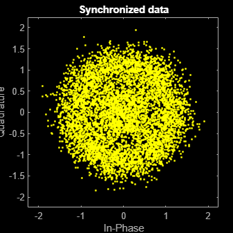
Plot the constellation of the synchronized data and compute the BER and PER.
% Synchronized data constellation plot
figure;
scatterplot(phaseCompOut);
title("Synchronized data");
% Error metrics display
% For GS continuous streams
if strcmpi(cfgDVBS2.StreamFormat,"GS") && ~rxParams.UPL
    if (simParams.numFrames-rxParams.totalSyncFrames == numFramesLost)
        fprintf("All frames are lost. No bits are retrieved from BB frames.")
    else
        ber = bitsErr/((dataStInd-rxParams.totalSyncFrames)*dataSize);
        fprintf("EsNo (dB): %1.2e\n",simParams.EsNodB)
        fprintf("%1.2e  BER           : %1.2e\n",ber)
    end
else
    % For GS and TS packetized streams
    if pktsRec == 0
        fprintf("All frames are lost. No packets are retrieved from BB frames.")
    else
        if strcmpi(cfgDVBS2.StreamFormat,"TS")
            pktLen = 1504;
        else
            pktLen = cfgDVBS2.UPL;      % UP length including sync byte
        end
        ber = bitsErr/(pktsRec*pktLen);
        per = pktsErr/pktsRec;
        fprintf("EsNo (dB): %1.2e\n",simParams.EsNodB)
        fprintf("PER: %1.2e\n",per)
        fprintf("BER: %1.2e\n",ber)
    end
end
EsNo (dB): 9.10e+00
PER: 0.00e+00
BER: 0.00e+00
One 16APSK 2/3 normal PL frames can accommodate 28 packets of size 1504 bits. The example runs for 500 frames that is 21.056e6 bits for several EsNodB points. Because this simulation takes a long time to run, this example provides only the results stored in a MAT-file.
load berResults.mat ber16APSK per16APSK EsNodB16APSK
berFig = figure;
semilogy(EsNodB16APSK,ber16APSK);
grid on;
xlabel("E_s/N_0 (dB)");
ylabel("BER");
title("BER plot");

perFig = figure;
semilogy(EsNodB16APSK,per16APSK);
grid on;
xlabel("E_s/N_0 (dB)");
ylabel("PER");
title("PER plot");

Further Exploration
The operating range of the DVB-S2 standard being very low requires the normalized loop bandwidth of the symbol synchronizer and coarse FLL to be very small for accurate estimation. These parameters are set via rxParams.symbSyncLoopBW and rxParams.carrSyncLoopBW.
Configure Carrier Synchronization Parameters
FLL tracking performance is calculated across multiple frames and a convergence criterion is designed when to move to the next stage, fine frequency offset compensation. Use "Coarse Frequency Locked Loop Characteristics" plot to visualize coarse frequency offset estimation.
Fine frequency offset is averaged over multiple pilot blocks on a frame by frame basis. When the estimated value converges in the order of 1e-5 across multiple frames, it is considered as fine frequency offset estimate. Since, proper phase offset estimation can happen only when residual carrier frequency offset is less than 0.02% of symbol rate, this convergence criterion is used.
Fine phase compensation PLL is used for only 16 APSK and 32 APSK modulation schemes with substantial phase noise.
After refining the synchronization parameters set in the rxParams structure, perform the BER simulation for the updated configuration.
Supporting Files
The example uses these helper functions:
HelperDVBS2RxInputGenerate.m: Generate DVB-S2 waveform samples distorted with RF impairments and structure of parameters for receiver processingHelperDVBS2PhaseNoise.m: Generate phase noise samples for different DVB-S2 phase noise masks and apply it to the input signalHelperDVBS2Synchronizer.m: Perform matched filtering, symbol timing synchronization, and coarse frequency estimation and correctionHelperDVBS2FrameSynchronizer.m: Perform frame synchronization and detect the start of frameHelperDVBS2FineFreqEst.m: Estimate fine frequency offsetHelperDVBS2PhaseEst.m: Estimate carrier phase offsetHelperDVBS2PhaseCompensate.m: Perform carrier phase compensationHelperDVBS2FinePhaseCompensator.m: Perform fine carrier phase error tracking and compensation for APSK modulation schemesHelperDVBS2NoiseVarEstimate.m: Estimate noise variance of received data
References
ETSI Standard EN 302 307-1 V1.4.1(2014-11). Digital Video Broadcasting (DVB); Second Generation Framing Structure, Channel Coding and Modulation Systems for Broadcasting, Interactive Services, News Gathering and other Broadband Satellite Applications (DVB-S2).
ETSI Standard TR 102 376-1 V1.2.1(2015-11). Digital Video Broadcasting (DVB); Implementation Guidelines for the Second Generation System for Broadcasting, Interactive Services, News Gathering and other Broadband Satellite Applications (DVB-S2).
Mengali, Umberto, and Aldo N.D'Andrea. Synchronization Techniques for Digital Receivers. New York: Plenum Press,1997.
E. Casini, R. De Gaudenzi, and Alberto Ginesi. "DVB‐S2 modem algorithms design and performance over typical satellite channels." International Journal of Satellite Communications and Networking 22, no. 3 (2004): 281-318.
Michael Rice, Digital Communications: A Discrete-Time Approach. New York: Prentice Hall, 2008.
Local functions
function dfl = getDFL(modCod,fecFrame)
% Get data field length
if strcmp(fecFrame,"normal")
    nDefVal = [16008 21408 25728 32208 38688 43040 48408 51648 53840 57472 ...
        58192 38688 43040 48408 53840 57472 58192 43040 48408 51648 53840 ...
        57472 58192 48408 51648 53840 57472 58192] - 80;
else
    nDefVal = [3072 5232 6312 7032 9552 10632 11712 12432 13152 14232 0 ...
        9552 10632 11712 13152 14232 0 10632 11712 12432 13152 14232 0 11712 ...
        12432 13152 14232 0] - 80;
end
dfl = nDefVal(modCod);
end
See Also
Objects
Topics
- DVB-S2 Link Simulation with RF Impairments and Non-Pilot-Aided Corrections
- DVB-S2X Link Simulation with RF Impairments and Corrections for Regular Frames
- DVB-S2X Link Simulation with RF Impairments and Corrections for VL-SNR Frames
- DVB-S2X Link Simulation with RF Impairments and Corrections in Wideband Mode
- DVB-S2 HDL Receiver