End-to-End DVB-S2X Simulation with RF Impairments and Corrections for Regular Frames
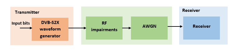
This example shows how to measure the bit error rate (BER) and packet error rate (PER) of a single stream Digital Video Broadcasting Satellite Second Generation extended (DVB-S2X) link that has constant coding and modulation for regular frames. The example describes the symbol timing and carrier synchronization strategies in detail emphasizing on how to estimate the RF front-end impairments under heavy noise conditions. The single stream signal adds RF front-end impairments and then passes the waveform through an additive white Gaussian noise (AWGN) channel.
Introduction
The DVB-S2X standard, an extension of the DVB-S2 specification, enhances the support provided for core DVB-S2 applications and improves overall efficiency over satellite links. The DVB-S2X standard supports these additional features:
More granularity of modulation and code rates
Smaller filter roll-off options for better utilization of bandwidth
Constellations optimized for linear and nonlinear channels
More scrambling options for critical co-channel interference scenarios
DVB-S2X caters to a variety of different target applications, and the receivers are subjected to different types and levels of RF impairments based on the application used. This example designs the synchronization aspects of a DVB-S2X receiver used for core DVB-S2 applications. The example supports the newer code rates, higher modulation schemes such as 64, 128 and 256 APSK, and smaller filter roll-off options.
ETSI EN 302 307-2 Section 6 Table 20a and Table 20c [1] summarizes the Quasi-Error-Free (QEF) performance requirement over an AWGN channel for different modulation schemes and code rates. The operating range for different transmission modes can be considered as +3 or -2 dB from the point where QEF performance is observed. Because the operating range is low, carrier and symbol timing synchronization strategies are challenging design problems.
This diagram summarizes the example workflow.
Main Processing Loop
The example processes 30 physical layer (PL) frames of data with the set to 25 dB, and then computes the BER and PER. Carrier frequency offset, sampling clock offset, and phase noise impairments are applied to the modulated signal, and AWGN is added to the signal.
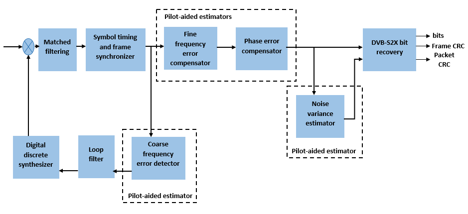
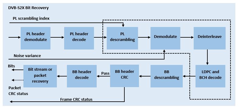
At the receiver, after matched filtering, timing and carrier recovery operations are run to recover the transmitted data. To extract PL frames, the distorted waveform is processed through various timing and carrier recovery strategies The carrier recovery algorithms are pilot-aided. To decode the data frames, the physical layer transmission parameters, such as modulation scheme, code rate, and FEC frame type, are recovered from the PL header. To regenerate the input bit stream, the baseband (BB) header is decoded.
Because the DVB-S2X standard supports packetized and continuous modes of transmission, the BB frame can be either a concatenation of user packets or a stream of bits. The BB header is recovered to determine the mode of transmission. If the BB frame is a concatenation of user packets, the packet cyclic redundancy check (CRC) status of each packet is returned along with the decoded bits, and then the PER and BER are measured.
These block diagrams show the synchronization and input bit recovery workflows.
Download DVB-S2X LDPC Parity Matrices Data Set
This example loads a MAT-file with DVB-S2X LDPC parity matrices. If the MAT-file is not available on the MATLAB® path, use these commands to download and unzip the MAT-file.
if ~exist('dvbs2xLDPCParityMatrices.mat','file')
    if ~exist('s2xLDPCParityMatrices.zip','file')
        url = 'https://ssd.mathworks.com/supportfiles/spc/satcom/DVB/s2xLDPCParityMatrices.zip';
        websave('s2xLDPCParityMatrices.zip',url);
        unzip('s2xLDPCParityMatrices.zip');
    end
    addpath('s2xLDPCParityMatrices');
end
DVB-S2X Configuration in Pilot-Aided Mode
Specify the cfgDVBS2X structure to define DVB-S2X transmission configuration parameters. PLSDecimalCode 129 and 131 are not supported because they are used for generating VL-SNR frames. Only the regular frames are supported.
cfgDVBS2X.StreamFormat ="TS" ; cfgDVBS2X.PLSDecimalCode = 191; % 64APSK 7/9 with pilots cfgDVBS2X.DFL = 50128; cfgDVBS2X.ScalingMethod =
"Unit average power"; cfgDVBS2X.RolloffFactor = 0.35; cfgDVBS2X.SamplesPerSymbol = 2
cfgDVBS2X = struct with fields:
        StreamFormat: "TS"
      PLSDecimalCode: 191
                 DFL: 50128
       ScalingMethod: "Unit average power"
       RolloffFactor: 0.3500
    SamplesPerSymbol: 2
Simulation Parameters
The DVB-S2X standard supports flexible channel bandwidths. Use a typical channel bandwidth such as 36 MHz. The channel bandwidth can be varied. The coarse frequency synchronization algorithm implemented in this example can track carrier frequency offsets up to 11% of the input symbol rate. The symbol rate is calculated as B/(1+R), where B is the channel bandwidth, and R is the transmit filter roll-off factor. The algorithms implemented in this example can correct the sampling clock offset up to 10 ppm.
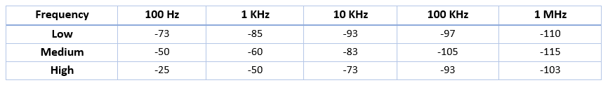
simParams.sps = cfgDVBS2X.SamplesPerSymbol; % Samples per symbol simParams.numFrames = 30; % Number of frames to be processed simParams.chanBW = 36e6; % Channel bandwidth in Hertz simParams.cfo = 2e6; % Carrier frequency offset in Hertz simParams.sco = 2; % Sampling clock offset in parts % per million simParams.phNoiseLevel ="Low"; % Phase noise level provided as % "Low", "Medium", or "High" simParams.EsNodB = 25; % Energy per symbol to noise ratio % in decibels
This table defines the phase noise mask (dBc/Hz) used to generate the phase noise applied to the transmitted signal. These noise masks are taken from ETSI TR 102 376-1 Section 4.3.2.1.3 Figure 12 [2].
Generate DVB-S2X Waveform Distorted with RF Impairments
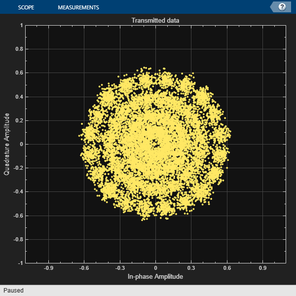
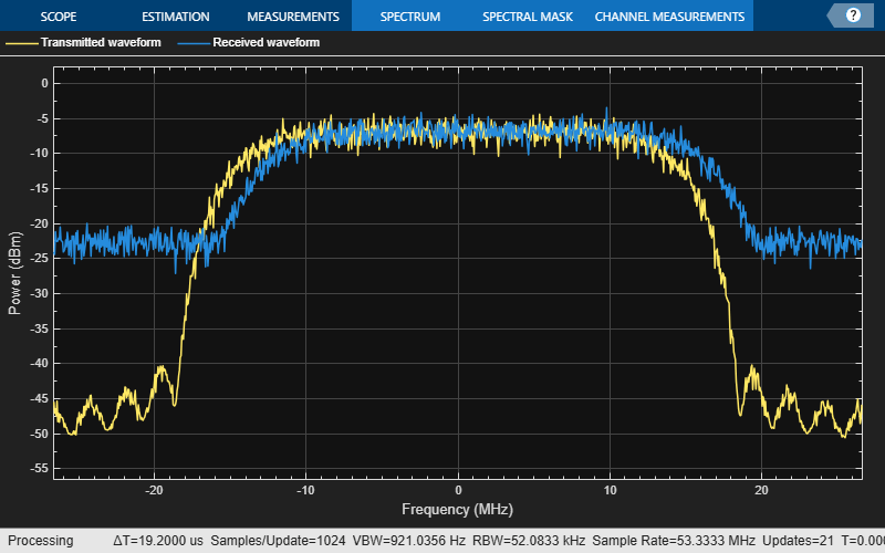
To create a DVB-S2X waveform, use the HelperDVBS2XRxInputGenerate helper function with the simParams and cfgDVBS2X structures as inputs. The function returns the data signal, transmitted and received waveforms, physical layer configuration parameters as a structure, and a receiver processing structure. The received waveform is impaired with carrier frequency, timing phase offsets, and phase noise and then passed through an AWGN channel. The receiver processing parameters structure, rxParams, includes the reference pilot fields, pilot indices, counters, and buffers. Plot the constellation of the received symbols and the spectrum of the transmitted and received waveforms.
[data,txOut,rxIn,phyConfig,rxParams] = HelperDVBS2XRxInputGenerate(cfgDVBS2X,simParams);
disp(phyConfig)
              FECFrame: "normal"
      ModulationScheme: "64APSK"
    LDPCCodeIdentifier: "7/9"
% Received signal constellation plot
rxConst = comm.ConstellationDiagram(Title = "Received data", ...
    AxesLimits = [-1 1], ...
    ShowReferenceConstellation = false, ...
    SamplesPerSymbol = simParams.sps);
rxConst(rxIn(1:length(txOut)))
% Transmitted and received signal spectrum visualization
Rsymb = simParams.chanBW/(1 + cfgDVBS2X.RolloffFactor);
Fsamp = Rsymb*simParams.sps;
specAn = spectrumAnalyzer(SampleRate = Fsamp, ...
    ChannelNames = ["Transmitted waveform" "Received waveform"], ...
    ShowLegend = true);
specAn([txOut,rxIn(1:length(txOut))]);
Configure Receiver Parameters
At the receiver, symbol timing synchronization is performed on the received data and is then followed by frame synchronization. The receiver algorithms include coarse and fine frequency impairment correction algorithms. The carrier frequency estimation algorithm can track carrier frequency offsets up to 20% of the input symbol rate. The coarse frequency estimation, implemented as a frequency locked loop (FLL), reduces the frequency offset to a level that the fine frequency estimator can track. The preferred loop bandwidth for symbol timing and coarse frequency compensation depends on the setting.
When you decrease , reduce the loop bandwidth to filter out more noise during acquisition. The number of frames required for the symbol synchronizer and coarse FLL to converge depends on the loop bandwidth setting. For weaker set rxParams.symbSyncLoopBW = 1e-4 and set rxParams.symbSyncLock = ceil(1e5/rxParams.plFrameSize).
The frame synchronization uses the PL header. Because the carrier synchronization is data-aided, the frame synchronization must detect the start of frame accurately. plays a crucial role in determining the accuracy of the frame synchronization. When QPSK modulated frames are being recovered at values below 3 dB, the frame synchronization must be performed on multiple frames for accurate detection.
The fine frequency estimation can track carrier frequency offsets up to 4% of the input symbol rate. The fine frequency estimation must process multiple pilot blocks for the residual carrier frequency offset to be reduced to levels acceptable for the phase estimation algorithm. The phase estimation algorithm can handle residual carrier frequency error less than 0.02% of the input symbol rate.
These settings are assigned in the rxParams structure for synchronization processing. For details on how to set these parameters for low values, see the Further Exploration section.
rxParams.carrSyncLoopBW = 1e-3;             % Coarse frequency estimator loop bandwidth
                                            % normalized by symbol rate
rxParams.symbSyncLoopBW = 8e-3;             % Symbol timing synchronizer loop bandwidth
                                            % normalized by symbol rate
rxParams.symbSyncLock  = 8;                 % Number of frames required for symbol timing
                                            % error convergence
rxParams.frameSyncLock = 1;                 % Number of frames required for frame
                                            % synchronization

% Total frames taken for symbol timing and frame synchronization to happen
rxParams.initialTimeSync = rxParams.symbSyncLock + rxParams.frameSyncLock;
% Initialize number of frames required for coarse carrier synchronization
% to total number of frames processed in simulation
rxParams.initialTimeFreqSync = simParams.numFrames;

% Create time frequency synchronization System object by using
% HelperDVBS2TimeFreqSynchronizer helper object
timeFreqSync = HelperDVBS2TimeFreqSynchronizer( ...
    CarrSyncLoopBW = rxParams.carrSyncLoopBW, ...
    SymbSyncLoopBW = rxParams.symbSyncLoopBW, ...
    SamplesPerSymbol = simParams.sps, ...
    DataFrameSize = rxParams.xFecFrameSize, ...
    SymbSyncTransitFrames = rxParams.symbSyncLock, ...
    FrameSyncAveragingFrames = rxParams.frameSyncLock);

% Initialize error computing parameters
[numFramesLost,pktsErr,bitsErr,pktsRec] = deal(0);

% Initialize data indexing variables
stIdx = 0;
% Variables for storing symbol synchronization output length, estimated coarse
% frequency offset, and average coarse frequency offset for every PL frame
[symSyncOutLen,cCFOEst,cCFOEstMean] = deal([]);
% Boolean variable to identify whether simulation has reached last frame, coarse
% frequency offset tracking, and fine frequency offset estimation has
% converged
[isLastFrame,isCoarseFreqLocked,isFineFreqLocked] = deal(false);
% Initialize the variable to store estimated fine frequency offset across
% PL frames
rxParams.fineFreqEstTemp = zeros(simParams.numFrames-rxParams.initialTimeSync,1);
rxParams.totalSyncFrames = simParams.numFrames;
% Counter to keep track of how many PL frames are used for fine frequency
% offset estimation
numFreqEst = 0;
% For short FEC frames, more PL frames are required to observe the frequency
% offset estimation performance
if cfgDVBS2X.PLSDecimalCode > 215
    cF = 5;
    fF = 4;
else
    cF = 3;
    fF = 3;
end
dataSize = rxParams.inputFrameSize;
plFrameSize = rxParams.plFrameSize;
Timing and Carrier Synchronization and Data Recovery
To synchronize the received data and recover the input bit stream, the distorted DVB-S2X waveform samples are processed one frame at a time by following these steps.
Apply matched filtering, outputting at the rate of two samples per symbol.
Apply symbol timing synchronization using the Gardner timing error detector with an output generated at the symbol rate. The Gardner TED is not data-aided, so it is performed before carrier synchronization.
Apply frame synchronization to detect the start of frame and to identify the pilot positions.
Estimate and apply coarse frequency offset correction.
Estimate and apply fine frequency offset correction.
Estimate and compensate for residual carrier frequency and phase noise.
Decode the PL header and compute the transmission parameters.
Demodulate and decode the PL frames.
Perform CRC check on the BB header, if the check passes, recover the header parameters.
Regenerate the input stream of data or packets from BB frames.
while stIdx < length(rxIn)

    % Use one DVB-S2X PL frame for each iteration.
    endIdx = stIdx + rxParams.plFrameSize*simParams.sps;

    % In the last iteration, all the remaining samples in the received
    % waveform are considered.
    isLastFrame = endIdx > length(rxIn);
    endIdx(isLastFrame) = length(rxIn);
    rxData = rxIn(stIdx+1:endIdx);

    % After coarse frequency offset loop is converged, the FLL works with a
    % reduced loop bandwidth.
    if rxParams.frameCount < rxParams.initialTimeFreqSync
        isCoarseFreqLocked = false;
    else
        isCoarseFreqLocked = true;
    end

    % Retrieve the last frame samples.
    if isLastFrame
        resSymb = plFrameSize - length(rxParams.cfBuffer);
        resSampCnt = resSymb*rxParams.sps - length(rxData);
        if resSampCnt >= 0    % Inadequate number of samples to fill last frame
            syncIn = [rxData; zeros(resSampCnt, 1)];
        else                  % Excess samples are available to fill last frame
            syncIn = rxData(1:resSymb*rxParams.sps);
        end
    else
        syncIn = rxData;
    end

    % Apply matched filtering, symbol timing synchronization, frame
    % synchronization, and coarse frequency offset compensation.
    if rxParams.frameCount > 1
     [coarseFreqSyncOut,syncIndex,phEst] = timeFreqSync(syncIn,isCoarseFreqLocked);
        % Calculate coarse frequency offset estimate from phaseEst
        coarseCFOEst = diff(phEst(1:simParams.sps:end)/(2*pi));
        if rxParams.frameCount <= rxParams.initialTimeSync
           symSyncOutLen = [symSyncOutLen;length(coarseFreqSyncOut)];
            if any(abs(diff(symSyncOutLen(1:rxParams.frameCount-1))) > 5)
                error("Symbol timing synchronization failed. The loop will not " + ...
                    "converge. No frame will be recovered. Update the symbSyncLoopBW " + ...
                    "parameter according to the EsNo setting for proper loop convergence.");
            end
        end
        if rxParams.frameCount > rxParams.initialTimeSync + 1
            cCFOEstMean=[cCFOEstMean;mean(coarseCFOEst)]; %#ok<*AGROW>
            cCFOEst = [cCFOEst;coarseCFOEst];
            % Check for FLL convergence based on estimated coarse frequency
            % offset values across frames
            if length(cCFOEstMean) > cF
                diffVal = diff(abs(cCFOEstMean));
                if all(diffVal(end-(cF-1):end) < mean(diffVal)) && ~isCoarseFreqLocked
                    isCoarseFreqLocked = true;
                    rxParams.initialTimeFreqSync = rxParams.frameCount;
                elseif isLastFrame && ~isCoarseFreqLocked
                    fprintf("%s\n",["Coarse frequency error estimation failed. Try analyzing the cCFOEst " ...
                        "across frames and see whether carrier synchronization is properly done. Try reducing the " ...
                        "carrSyncLoopBW parameters. Check with proper frame synchronization happened"]);
                end
            end
        end
    rxParams.syncIndex = syncIndex;
    % The PL frame start index lies somewhere in the middle of the chunk being processed.
    % From fine frequency estimation onwards, the processing happens as a PL frame.
    % A buffer is used to store symbols required to fill one PL frame.
    if isLastFrame
        resCnt = resSymb - length(coarseFreqSyncOut);
        if resCnt <= 0
            fineFreqIn = [rxParams.cfBuffer; coarseFreqSyncOut(1:resSymb)];
        else
            fineFreqIn = [rxParams.cfBuffer; coarseFreqSyncOut; zeros(resCnt, 1)];
        end
    elseif rxParams.frameCount > 1
        fineFreqIn = [rxParams.cfBuffer; coarseFreqSyncOut(1:rxParams.plFrameSize-length(rxParams.cfBuffer))];
    end

    % Estimate the fine frequency error by using the HelperDVBS2FineFreqEst
    % helper function.
    % Add 1 to the conditional check because the buffer used to get one PL
    % frame introduces a delay of one to the loop count.
   if (rxParams.frameCount > rxParams.initialTimeFreqSync + 1) && ...
                ~isFineFreqLocked
            rxParams.fineFreqCorrVal = HelperDVBS2FineFreqEst( ...
                fineFreqIn(rxParams.pilotInd),rxParams.numPilotBlks, ...
                rxParams.refPilots,rxParams.fineFreqCorrVal);
            % Normalize the frequency estimate by the input symbol rate
            % freqEst = angle(R)/(pi*(N+1)), where N (18) is the number of elements
            % used to compute the mean of auto correlation (R) in
            % HelperDVBS2FineFreqEst.
            freqEst = angle(rxParams.fineFreqCorrVal)/(pi*(19));
            rxParams.fineFreqEstTemp(1:end-1) = rxParams.fineFreqEstTemp(2:end);
            rxParams.fineFreqEstTemp(end) = freqEst;
            numFreqEst = numFreqEst+1;
            fprintf("Estimated carrier frequency offset in Hz = %f\n",(coarseCFOEst(end)+freqEst).*Rsymb);
            % Check normalized fine frequency offset estimation has converged within
            % an order of 1e-4
            if numFreqEst>=5
                cg = abs(diff(rxParams.fineFreqEstTemp));
                if all(cg(end-fF:end) < 1e-4)
                    isFineFreqLocked = true;
                    rxParams.totalSyncFrames = rxParams.frameCount;
                      dataStInd = rxParams.frameCount;
                elseif isLastFrame && ~isFineFreqLocked
                    fprintf("%s\n",["Fine frequency error estimation failed. Try analyzing the " ...
                        "pilot fields in the PL frame to debug the issue."])
                end
            end
        end


    if isFineFreqLocked
        % Normalize the frequency estimate by the input symbol rate
        % freqEst = angle(R)/(pi*(N+1)) where N (18) is the number of elements
        % used to compute the mean of auto correlation (R) in
        % HelperDVBS2FineFreqEst.
        freqEst = angle(rxParams.fineFreqCorrVal)/(pi*(19));

        % Generate the symbol indices using frameCount and plFrameSize.
        % Subtract 2 from the rxParams.frameCount because the buffer used to get one
        % PL frame introduces a delay of one to the count.
        ind = (rxParams.frameCount-2)*plFrameSize:(rxParams.frameCount-1)*plFrameSize-1;
        phErr = exp(-1j*2*pi*freqEst*ind);
        fineFreqOut = fineFreqIn.*phErr(:);

        % Estimate the phase error estimation by using the HelperDVBS2PhaseEst
        % helper function.
        [phEstRes,rxParams.prevPhaseEst] = HelperDVBS2PhaseEst( ...
            fineFreqOut,rxParams.refPilots,rxParams.prevPhaseEst, rxParams.pilotInd);

        % Compensate for the residual frequency and phase offset by using
        % the
        % HelperDVBS2PhaseCompensate helper function.
        % Use two frames for initial phase error estimation. Starting with the
        % second frame, use the phase error estimates from the previous frame and
        % the current frame in compensation.
        % Add 2 to the frame count comparison to account for delays: One
        % frame due to rxParams.cfBuffer delay and two frames used for phase
        % error estimate.
        if rxParams.frameCount >= rxParams.totalSyncFrames + 2
            phaseCompOut = HelperDVBS2PhaseCompensate(rxParams.ffBuffer, ...
                rxParams.pilotEst,rxParams.pilotInd,phEstRes(2));
        end

        rxParams.ffBuffer = fineFreqOut;
        rxParams.pilotEst = phEstRes;

        % The phase compensation on the data portion is performed by
        % interpolating the phase estimates computed on consecutive pilot
        % blocks. The second phase estimate is not available for the data
        % portion after the last pilot block in the last frame. Therefore,
        % the slope of phase estimates computed on all pilot blocks in the
        % last frame is extrapolated and used to compensate for the phase
        % error on the final data portion.
        if isLastFrame
            pilotBlkLen = 36;                         % Symbols
            pilotBlkFreq = 1476;                      % Symbols
            avgSlope = mean(diff(phEstRes(2:end)));
            chunkLen = rxParams.plFrameSize - rxParams.pilotInd(end) + ...
                rxParams.pilotInd(pilotBlkLen);
            estEndPh = phEstRes(end) + avgSlope*chunkLen/pilotBlkFreq;
            phaseCompOut1 = HelperDVBS2PhaseCompensate(rxParams.ffBuffer, ...
                rxParams.pilotEst,rxParams.pilotInd,estEndPh);
        end
    end

    % Recover the input bit stream.
    if rxParams.frameCount >= rxParams.totalSyncFrames + 2
        isValid = true;
        if isLastFrame
            syncOut = [phaseCompOut;phaseCompOut1];
        else
            syncOut = phaseCompOut;
        end
    else
        isValid = false;
        syncOut = [];
    end

    % Update the buffers and counters.
    rxParams.cfBuffer = coarseFreqSyncOut(rxParams.syncIndex:end);

    if isValid  % Data valid signal

        % Decode the PL header by using the dvbsPLHeaderRecover function
        rxPLSCode = syncOut(1:90); % First 90 symbols of frame is PL header
        phyParams = dvbsPLHeaderRecover(rxPLSCode,Mode="DVB-S2/S2X regular");
        plsDecCode = phyParams.PLSDecimalCode;
        % Validate the decoded PL header.
        if plsDecCode ~= cfgDVBS2X.PLSDecimalCode
            fprintf("%s\n","PL header decoding failed")
            dataStInd = dataStInd + 1;
        else % Demodulation and decoding

                rxFrame = syncOut(1:plFrameSize);
                % Estimate noise variance by using
                % HelperDVBS2NoiseVarEstimate helper function.
                nVar = HelperDVBS2NoiseVarEstimate(rxFrame,rxParams.pilotInd,...
                    rxParams.refPilots,rxParams.normFlag);
                % Recover the input bit stream by using the
                % dvbs2xBitRecover function.
                [decBitsTemp, isFrameLost, pktCRC]  = dvbs2xBitRecover(rxFrame,nVar);
                decBits = decBitsTemp{:};

                if ~isFrameLost && length(decBits) ~= dataSize
                    isFrameLost = true;
                end

                if ~(strcmpi(cfgDVBS2X.StreamFormat,"GS") && ~rxParams.UPL)
                    % Compute the packet error rate for TS or GS packetized
                    % mode.
                    pktsErr = pktsErr + numel(pktCRC{:}) - sum(pktCRC{:});
                    pktsRec = pktsRec + numel(pktCRC{:});
                end

                if ~isFrameLost
                    ts = sprintf("%s","BB header decoding passed.");
                else
                    ts = sprintf("%s","BB header decoding failed.");
                end

                % Compute the number of frames lost. CRC failure of baseband header
                % is considered a frame loss.
                numFramesLost = isFrameLost + numFramesLost;

                fprintf("%s(Number of frames lost = %1d)\n",ts,numFramesLost)
                % Compute the bits in error.
                bitInd = (dataStInd-1)*dataSize+1:dataStInd*dataSize;
                if isLastFrame && ~isFrameLost
                    bitsErr = bitsErr + sum(data(bitInd) ~= decBits);
                else
                    if ~isFrameLost
                        bitsErr = bitsErr + sum(data(bitInd) ~= decBits);
                    end
                end
                dataStInd = dataStInd + 1;
        end
    end
    end
    stIdx = endIdx;
     rxParams.frameCount = rxParams.frameCount + 1;
end
Estimated carrier frequency offset in Hz = 1996109.143279
Estimated carrier frequency offset in Hz = 1998196.196545
Estimated carrier frequency offset in Hz = 1998807.660734
Estimated carrier frequency offset in Hz = 1999231.137523
Estimated carrier frequency offset in Hz = 1999227.365179
BB header decoding passed.(Number of frames lost = 0)
BB header decoding passed.(Number of frames lost = 0)
BB header decoding passed.(Number of frames lost = 0)
BB header decoding passed.(Number of frames lost = 0)
BB header decoding passed.(Number of frames lost = 0)
BB header decoding passed.(Number of frames lost = 0)
BB header decoding passed.(Number of frames lost = 0)
BB header decoding passed.(Number of frames lost = 0)
Visualization and Error Logs
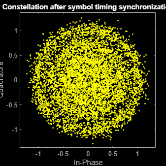
Plot the constellation of the synchronized data and compute the BER and PER.
% Synchronized data constellation plot
syncConst = comm.ConstellationDiagram(Title = "Synchronized data", ...
    AxesLimits = [-1.7 1.7], ...
    ShowReferenceConstellation = false);
syncConst(syncOut)
% Error metrics display
% For GS continuous streams
if strcmpi(cfgDVBS2X.StreamFormat,"GS") && ~rxParams.UPL
    if (simParams.numFrames-rxParams.totalSyncFrames == numFramesLost)
        fprintf("All frames are lost. No bits are retrieved from BB frames.")
    else
        ber = bitsErr/((dataStInd-rxParams.totalSyncFrames)*dataSize);
        fprintf("BER           : %1.2e\n",ber)
    end
else
    % For GS and TS packetized streams
    if pktsRec == 0
        fprintf("All frames are lost. No packets are retrieved from BB frames.")
    else
        if strcmpi(cfgDVBS2X.StreamFormat,"TS")
            pktLen = 1504;
        else
            pktLen = cfgDVBS2X.UPL;      % UP length including sync byte
        end
        ber = bitsErr/(pktsRec*pktLen);
        per = pktsErr/pktsRec;
        fprintf("PER: %1.2e\n",per)
        fprintf("BER: %1.2e\n",ber)
    end
end
PER: 0.00e+00
BER: 0.00e+00
Further Exploration
For BER simulations in AWGN assuming perfect synchronization, use the dvbs2xBitRecover function to evaluate the receiver performance. See the examples provided in the M-help section of the dvbs2xBitRecover function. For details on how to configure the synchronization parameters of the rxParams for other cfgDVBS2X and simParams settings, see the 'Further Exploration section' of End-to-End DVB-S2 Simulation with RF Impairments and Corrections on how to configure the synchronization parameters of rxParams for other cfgDVBS2X and simParams settings.
Supporting Files
The example uses these helper functions:
HelperDVBS2XRxInputGenerate.m: Generate DVB-S2X waveform samples distorted with RF impairments and structure of parameters for receiver processing
HelperDVBS2PhaseNoise.m: Generate phase noise samples for different DVB-S2X phase noise masks and apply it to the input signal
HelperDVBS2TimeFreqSynchronizer.m: Perform matched filtering, symbol timing synchronization, frame synchronization, and coarse frequency estimation and correction
HelperDVBS2FrameSync.m: Perform frame synchronization and detect the start of frame
HelperDVBS2FineFreqEst.m: Estimate fine frequency offset
HelperDVBS2PhaseEst.m: Estimate carrier phase offset
HelperDVBS2PhaseCompensate.m: Perform carrier phase compensation
HelperDVBS2NoiseVarEstimate.m: Estimate noise variance of received data
References
ETSI Standard EN 302 307-2 V1.1.1(2015-11). Digital Video Broadcasting (DVB); Second Generation Framing Structure, Channel Coding and Modulation Systems for Broadcasting, Interactive Services, News Gathering and other Broadband Satellite Applications; Part 2: DVB-S2 extensions (DVB-S2X).
ETSI Standard TR 102 376-2 V1.2.1(2015-11). Digital Video Broadcasting (DVB); Implementation Guidelines for the Second Generation System for Broadcasting, Interactive Services, News Gathering and other Broadband Satellite Applications; Part 2: S2 extensions (DVB-S2X).
ETSI Standard TR 102 376-1 V1.2.1(2015-11). Digital Video Broadcasting (DVB); Implementation Guidelines for the Second Generation System for Broadcasting, Interactive Services, News Gathering and other Broadband Satellite Applications (DVB-S2).
Mengali, Umberto, and Aldo N.D'Andrea. Synchronization Techniques for Digital Receivers. New York: Plenum Press,1997.
E. Casini, R. De Gaudenzi, and Alberto Ginesi. "DVB‐S2 modem algorithms design and performance over typical satellite channels." International Journal of Satellite Communications and Networking 22, no. 3 (2004): 281-318.
Michael Rice, Digital Communications: A Discrete-Time Approach. New York: Prentice Hall, 2008.