addVisual
Add visual geometry data to rigid body
Description
addVisual(
adds the visuals of a geometry of the specified type body,type,parameters)type
and geometric parameters parameters to the specified rigid
body body.
addVisual(___,
specifies additional options using one or more name-value pair arguments.
Specify name-value pair arguments after all other input arguments.Name=Value)
addVisual(___,
specifies a homogeneous transformation for the geometry visual relative to the
body frame in addition to any combination of input arguments from previous
syntaxes.tform)
Examples
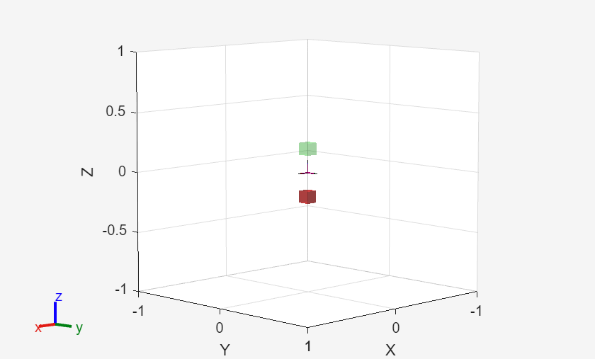
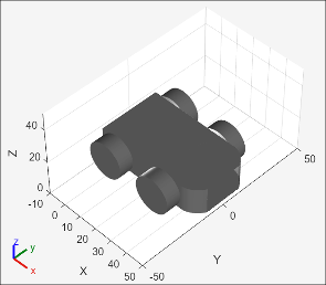
Create a rigid body tree robot model.
rbt = rigidBodyTree();
Add a body to the base of the robot.
body1 = rigidBody('Link1');Add a red visual box mesh to Link1 body with FaceAlpha set to 0.5 for 50% transparency. Add another visual box mesh and set the color to green and transparency to 20%.
Use trvec2tform function to define the position of each box.
boxdims = [0.1,0.1,0.1];

pose = trvec2tform([0,0,-0.2]);
addVisual(body1, 'Box', boxdims, pose, FaceColor=[1 0 0], FaceAlpha=0.5);

pose = trvec2tform([0,0,0.2]);
addVisual(body1, 'Box', boxdims, pose, FaceColor=[0 1 0], FaceAlpha=0.2);
Add the body 'Link1' to the robot model as a child to the robot's base.
addBody(rbt, body1, rbt.BaseName);
Visualize the robot with visual meshes.
show(rbt);
Input Arguments
Rigid body, specified as a rigidBody object.
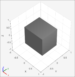
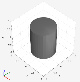
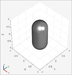
Geometry type for geometry, specified as one of these valid geometry type names:
| Geometry Type | Shape |
|---|---|
"Box" |
|
"Cylinder" |
|
"Capsule" |
|
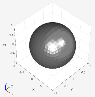
"Sphere" |
|
"Mesh" |
|
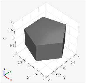
"RegularExtrusion" |
|
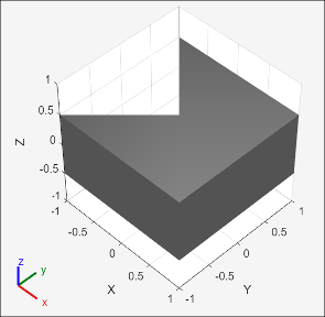
"GeneralExtrusion" |
|
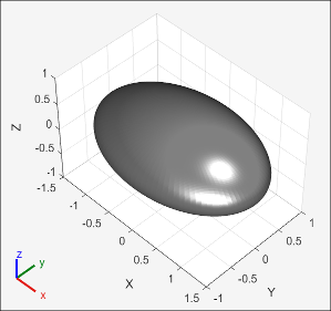
"Ellipsoid" |
|
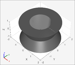
"RevolvedSolid" |
|
Data Types: char | string
Geometry parameters, specified as a numeric vector, numeric matrix, or
string scalar. The type input determines the format of
this value.
"Box"—[x y z]"Cylinder"—[radius length]"Capsule"—[radius length]"Sphere"—radius"Mesh"—"meshfilename"or{'meshfilename' scale}.'meshfilename'must either be an STL or DAE file name, specified as a string or character vector.scaleis the xyz-scale of the mesh's bounding box, specified as a three-element vector of positive numeric values. The scaling is along the axes of the origin frame of the rigid body."RegularExtrusion"—[numberofsides outerradius length]. It represents extruded geometry with a regular polygonal cross section."GeneralExtrusion"—[crosssection length]. It represents extruded geometry with an arbitrary polygonal cross-section.The
crossectionparameter is specified as a vector of N number of 2-D points where:N is greater than or equal to 3.
No two consecutive vertices coincide, including the first and last.
The ordering of vertices follows a right-handed boundary traversal.
The cross section must avoid self-intersection.
"Ellipsoid"—[x-radius y-radius z-radius]"RevolvedSolid"—crossectionfor fully revolved solid or[crossection revolutionangle]for partially revolved solid. The revolved solid represents a rotational sweep of a polygonal cross-section specified in the xz-plane.The
crossectionparameter is specified as a vector of N number of 2-D points where:N is greater than or equal to 3.
No two consecutive vertices coincide, including the first and last.
The ordering of vertices follows a right-handed boundary traversal.
The cross section must avoid self-intersection.
The cross section must entirely lie in the closed right plane (nonnegative x coordinates).
Example: addVisual(body,"mesh",{"meshName.stl",[0.5 1
1]})
Data Types: single | double | char | string
Mesh transformation relative to the body coordinate frame, specified as a frame name or 4-by-4 homogeneous transformation.
Name-Value Arguments
Version History
Introduced in R2017bSee Also
getVisual | addCollision | clearCollision | clearVisual | show | rigidBodyTree