Get Started with the Hydromechanical Valve Library
R2026bThe blocks in the Hydromechanical Valve library represent pieces of valves that you can combine in series to model a complete, customized valve. Use these blocks to simulate the effect that valve structure has on the flow metering areas, and the effect that the fluid forces have on the valve structure.
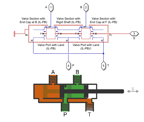
You can combine the hydromechanical valve blocks to visually replicate a valve schematic. For example, this figure shows a 4-way 3-position valve diagram and the equivalent valve constructed using components from the Hydromechanical Valve library.
Choosing Between Hydromechanical and Behavioral Valves
The Isothermal Liquid library also includes behavioral valve blocks, which model a complete valve. Behavioral valve blocks model the metering area and flow through the valve, but do not model forces. Use behavioral valves when:
You are parameterizing a valve based on a datasheet.
You are concerned about computational cost. Behavioral valves are much less computationally expensive.
You want to control the metering area directly by using a control signal or control pressure.
Use blocks from the Hydromechanical Valve library to construct a valve when:
You need to model mechanical forces such as springs and damping or fluid force on the valve.
You are designing a custom valve or building a valve that does not exist in the Isothermal Liquid library.
You need to track the position and forces of valve components, such as poppets or spools.
Hydromechanical Valve Composite Signals
In the Hydromechanical Valve library, each block has B and F ports, which are hydromechanical composite ports that each contain three nodes. Use the Hydromechanical Valve Interface (IL-PB) block to separate a hydromechanical composite port into its three base nodes. The ports comprise these nodes:
valve_body— Position-based translational node that represents the valve body. This node is usually stationary.spool— Position-based translational node that represents the moving valve element, such as a poppet or spool.fluid— Isothermal liquid node that represents the flow path inside the valve.
The valve_body and spool nodes are
position-based translational nodes. In the position-based translational domain, the
model tracks position and velocity relative to a global zero position. For more
information, see Modeling Mechanical Position-Based Translational Systems.
Block Connections
Like the blocks in the position-based translational mechanical library, arrange all hydromechanical valve blocks with port B on one side and port F on the other. To reverse the behavior of a block, do not rotate the block. Instead, select the corresponding reverse block from the library. For example, the Valve Section with End Cap at B (IL-PB) is the reverse of the Valve Section with End Cap at F (IL-PB) block.
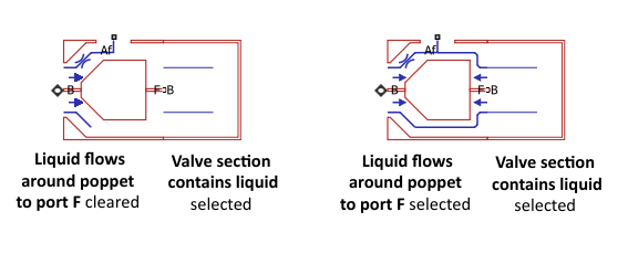
This image shows an example of two connected hydromechanical valve blocks. The outer edges of the blocks align with each other, as the figure on the left shows. However, ensure that the hydromechanical composite ports are connected, as the figure on the right shows.

Building Models That Use Hydromechanical Library Blocks
When using the blocks in the Hydromechanical Valve library, use a Valve Section with End Cap at B (IL-PB) or Valve Section with End Cap at F (IL-PB) block as the first and last component in the valve. The end cap blocks terminate the valve and also have optional ports that you can connect to a reference, source, or actuator. The Valve Section with End Cap at B (IL-PB), Valve Section with End Cap at F (IL-PB), Valve Section with Detached Shaft (IL-PB), and Valve Section with Rigid Shaft (IL-PB) blocks do not model pressure loss. Do not directly connect their Af ports to blocks that model volume, such as a reservoir, chamber, or tank. For more numerically robust results, first connect port Af to a block that models flow resistance, such as the Flow Resistance (IL), Pipe (IL), or Orifice (IL) blocks.
If a component contains fluid, ensure that the adjacent block also models fluid flow at the connected port. Block icons reflect the fluid flow and do not show blue isothermal liquid lines on any side that does not model it. If the adjacent port does model isothermal liquid flow, it shows blue isothermal liquid lines. If these lines do not match across adjacent blocks, there is an issue with the model. For example, in the figure below, the left Poppet with Seat at B (IL-PB) and Valve Section with End Cap at F (IL-PB) blocks are not properly configured. The figure on the right is properly configured. Because the Poppet with Seat at B (IL-PB) block Liquid flows around poppet to port F parameter is selected, port F of that block models fluid flow.
The Hydromechanical Valve block icons provide information on the valve characteristics. Restriction symbols along isothermal liquid lines indicate pressure loss. The length of a contiguous isothermal liquid line without restrictions is at the same pressure, no matter how long it is. Blue arrows represent pressure force on either the spool land or poppet. If one side of the valve element does not have blue arrows, that side is at atmospheric pressure.

