Partition Simscape Models Containing a Large Network into Multiple Smaller Networks
This example shows how to partition a solar power inverter model that contains a single large Simscape™ network into multiple networks. After you partition the network, you can run the Simscape HDL Workflow Advisor to generate the HDL implementation model. To learn how to run the Advisor for the model, see Generate HDL Code for Simscape Models with Multiple Networks.
Why Partition a Simscape Network
When your Simscape model contains many switching elements, the state-space representation can contain a large number of modes. The Simscape HDL Workflow Advisor simulates the Simscape model to calculate the number of modes that are relevant. Certain Simscape models can have a large number of modes that are relevant. The generated HDL implementation model for such a large design can consume a significant amount of resources, and the generated HDL implementation model may even fail to synthesize on the target FPGA device. To reduce the number of modes, you can partition the Simscape network in your model into multiple networks, and then run the Simscape HDL Workflow Advisor.
Open Solar Power Inverter Model with Single Network
To open the solar power inverter example model, run:
open_system('sschdlexSolarInverterSingleNetworkExample')
set_param('sschdlexSolarInverterSingleNetworkExample', 'SimulationCommand', 'Update')

The model consists of four parts: an inverter controller, a boost controller, a boost converter and full bridge inverter, and a solar panel. The solar panel is modeled in Simulink® by using lookup tables. The boost controller and inverter controller provide the control signals for the boost converter and the full bridge inverter, which is an H-bridge.
To see the boost converter and full bridge inverter, open the Network subsystem.
open_system('sschdlexSolarInverterSingleNetworkExample/Network')

Run Simscape HDL Workflow Advisor
1. To open the Simscape HDL Workflow Advisor for the model, enter:
sschdladvisor('sschdlexSolarInverterSingleNetworkExample')
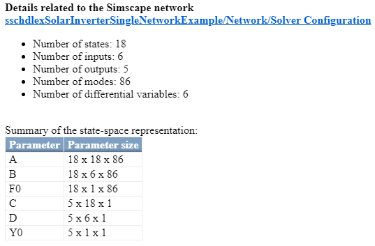
2. Run the workflow to the Extract discrete equations task. You see that the state-space representation uses 86 modes, which is a large number of modes.

Such a large number of modes can consume a significant amount of hardware resources, and may even cause the DUT subsystem in the HDL implementation model to fail to synthesize on the target FPGA device.
Generate HDL Implementation Model and View Resource Consumption
To see the resource consumption:
1. Run the Generate implementation model task. After the task passes, you see a link to the HDL implementation model gmStateSpaceHDL_sschdlexSolarInverterSingle. Click the link to open the HDL implementation model.
The model contains an HDL Subsystem block that models the state-space equations for the Simscape network. Open the generated HDL implementation model gmStateSpaceHDL_sschdlexSolarInverterSingle.
open_system('gmStateSpaceHDL_sschdlexSolarInverterSingle/Network')

2. Enable generation of the resource utilization report.
hdlset_param('gmStateSpaceHDL_sschdlexSolarInverterSingle', 'ResourceReport', 'on')
3. Generate code for the HDL Subsystem block.
makehdl('gmStateSpaceHDL_sschdlexSolarInverterSingle/Network/HDL Subsystem')
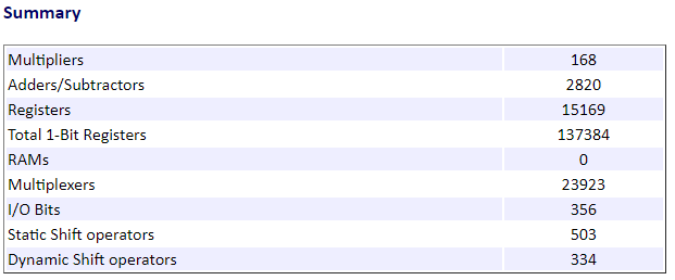
4. As you generate HDL code, open the Code Generation Report. The resource utilization report shows large numbers of multipliers, adders, and registers that might be used on the target FPGA device.

Partition Solar Inverter Network into Multiple Simscape Networks
To reduce the number of modes, you can partition the Simscape network inside the Network subsystem into two Simscape networks. To partition the network into multiple networks you can use a Network Coupler (Current-Voltage) (Simscape) block. The Network Coupler (Current-Voltage) block provides a starting point for you to split a Simscape™ network into two coupled networks at an electrical connection.
1. Identify the boundary for partitioning the network into multiple networks. To produce a Simscape model that contains multiple networks and effectively reduces the number of modes in the state-space representation, choose a boundary that produces identical or near identical partitions. That is, the number of switching elements on either side of the boundary are identical or nearly identical.
For the solar power inverter, you can choose the DC link capacitor between the full bridge inverter and the boost converter as the boundary for partitioning the network.

Once you choose the boundary, connect the Network Coupler (Current-Voltage) for partitioning the network into two Simscape networks.

2. After you partition the network, prepare the modified Simscape model for compatibility with the Simscape HDL Workflow Advisor. Use a Solver Configuration block for each partition of the network as the Simscape HDL Workflow Advisor uses the Solver Configuration block to identify each unique network in your Simscape model.
Open Solar Power Inverter Model with Multiple Networks
The single network model is now partitioned into multiple networks. To open the model containing multiple networks, enter:
open_system('sschdlexSolarInverterPartitionedNetworkExample')
To learn how you run the Simscape HDL Workflow Advisor and generate HDL code for this model, see Generate HDL Code for Simscape Models with Multiple Networks.