Guidelines for HDL Code Generation Using Stateflow Charts
These guidelines illustrate the recommended settings when using Stateflow® charts in your model. The Stateflow Chart block is available in the Stateflow block library. By using Stateflow charts, you can model delays in your Simulink® model.
Each guideline has a severity level that indicates the level of compliance requirements. To learn more, see HDL Modeling Guidelines Severity Levels.
Choose State Machine Type based on HDL Implementation Requirements
Guideline ID
2.9.1
Severity
Strongly Recommended
Description
HDL Coder™ supports code generation for Mealy and Moore Stateflow charts. MATLAB Function block is also available to
model Mealy or Moore state
machines.
To specify whether you want a Mealy or
Moore state machine, in the Chart (Stateflow) properties, specify the
State Machine Type. Do not use
Classic because it affects readability of the
generated HDL code. Choose the State Machine Type depending
on how you want the Stateflow semantics to map to a hardware implementation. See Hardware Realization of Stateflow Semantics.
When you use Mealy charts, the outputs depend on
the current state and inputs. By using Mealy charts,
you can more easily define state transitions which makes these charts more
flexible to use. The generated HDL code from Mealy
charts may be less readable.
For Moore charts, the outputs depend
only on the current state. The generated HDL code
from Moore charts is more readable.
Moore charts restrict flexibility in defining
state transitions.
Specify Block Configuration Settings of Stateflow Chart
Guideline ID
2.9.2
Severity
Strongly Recommended
Description
When you use Stateflow Chart (Stateflow) blocks in your model for HDL code generation, use these recommended settings:
For Action Language, use
MATLABFor Update method, use
DiscreteorInherited. Do not useContinuous.
Moore Chart
If you disable Initialize Outputs Every Time Chart Wakes Up, the generated HDL code includes additional registers for the state machine output values.
Disable Support Variable-Size Arrays.
Mealy Chart
If you disable Initialize Outputs Every Time Chart Wakes Up, the generated HDL code includes additional registers for the state machine output values.
Disable Enable Super Step Semantics.
Disable Support Variable-Size Arrays.
Enable Execute (enter) chart at initialization.
To make sure that these settings are specified for the Stateflow Chart, you can run the Check for Stateflow chart settings.
Data Type Settings and Casting in Stateflow Chart for HDL Code Generation
Guideline ID
2.9.3
Severity
Informative
Description
When you do not explicitly specify the data type of state and output variables in a Stateflow Chart that has MATLAB as the Action Language, the data type becomes double. If variables that have different data types are assigned to these Chart variables, a data type mismatch can occur, which can lead to simulation errors.
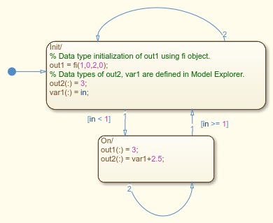
To avoid simulation errors, explicitly initialize the data type of the Chart variables by using fi objects, or specify their data type in Model Explorer. When performing assignments to variables of different types, you can perform data type conversion and initialization by using fi objects.
When you want to change the fi data type, you must specify the word lengths and fraction lengths for the types. For frequent data type conversions, you can instead cast the type to fi data types by using subscript(:). In this case, you can replace data type conversions with cast by subscript(:) in the Model Explorer. The value of the substitution source is then type-converted to that of the substitution target variable.
Note: For assignments to intermediate variables, you do not have to cast the data type.
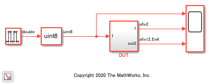
For an example that shows the different data type initialization methods, open the model hdlcoder_chart_datatype_casting.
open_system('hdlcoder_chart_datatype_casting')
set_param('hdlcoder_chart_datatype_casting', 'SimulationCommand', 'Update')

The DUT subsystem contains a Moore chart that shows how the output variables out1 and out2 and an internal variable var1 are defined. out1 type is explicitly specified by using a fi object, and out2 and var1 types are defined in the Model Explorer.
open_system('hdlcoder_chart_datatype_casting/DUT/Chart')

To generate HDL code for the DUT subsystem, run the makehdl function.
makehdl('hdlcoder_chart_datatype_casting/DUT')
Using Absolute Time Temporal Logic in Stateflow Charts
Guideline ID
2.9.4
Severity
Mandatory
Description
When you use absolute time temporal logic in your Stateflow Chart (Stateflow) blocks in your model for HDL code generation, use these settings.
For the sample rate of the chart:
If you use seconds (sec), then the sample time must be an integer 65535 or lower, or a decimal between 65.535 and 0.001 having no more than three decimal places.
If you use milliseconds (msec), the sample time must be a decimal between 65.535 and 0.001 having no more than three decimal places, or a decimal between 0.065535 and 0.000001 having no more than six decimal places.
If you use microseconds (usec), the sample time must be a decimal between 0.065535 and 0.000001 having no more than six decimal places, or a decimal between 0.000065535 and 0.000000001 having no more than nine decimal places.
If the sample time is an integer below 2^16, use
'sec'.If 1000 * sample time is an integer below 2^16, use
'sec'or'msec'.If 1000000 * sample time is an integer below 2^16, use
'msec'or'usec'.If 1000000000 * sample time is an integer below 2^16, use
'usec'.
Modeling Error (default) State in Stateflow Charts
Guideline ID
2.9.5
Severity
Informative
Description
When generating HDL code for Stateflow charts that have exclusive state decomposition, states are
represented by case statements. For example, a chart with three states,
A, B, and C,
results in a switch case:
CASE is_Chart IS
        WHEN IN_A =>
          is_Chart_next <= IN_B;
          y_tmp <= to_signed(16#00000002#, 32);
        WHEN IN_B =>
          is_Chart_next <= IN_C;
          y_tmp <= to_signed(16#00000003#, 32);
        WHEN OTHERS =>
          --case IN_C:
          y_tmp <= to_signed(16#00000003#, 32);
      END CASE;
It is useful to control which of the states corresponds to the default case of
the switch. For example, you can use the default state to model error behavior.
The state whose name is alphabetically last occurs in the default branch. In the
example code, the default branch is WHEN OTHERS=>.
If you are using variant transitions, an unreachable default state can be
eliminated in the HDL code. To avoid this, the selected default state must be
reachable. For example, you can connect the default state to another reachable
state and provide a transition that is always
false, such as 1 == 0. For more information, see Control Indicator Lamp Dimmer Using Variant Conditions (Stateflow).
Enable Clock-Driven Outputs of Stateflow Charts (Moore Charts Only)
Guideline ID
2.9.6
Severity
Informative
Description
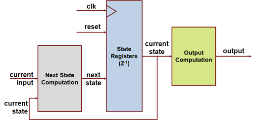
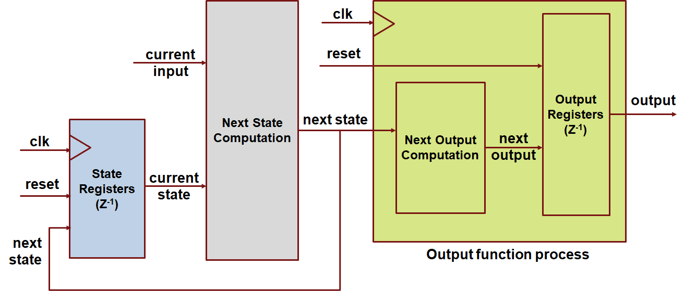
You can generate HDL code that has clock-driven output signals for Moore charts in Stateflow. Clock-driven outputs prevent combinatorial logic from driving the output and allow an immediate output update when the clock signal and state change. You can enable clock-driven outputs for Stateflow charts by using the Stateflow chart HDL block property ClockDrivenOutput. This option is available only for Moore charts.
When ClockDrivenOutput is off,
the HDL code generated from a Moore chart has this structure:

When you set ClockDrivenOutput to
on, HDL Coder adds an output register that updates when the state updates.
HDL Coder then assigns the final output variable a value from the
clock-driven register. The generated HDL code has this structure:

The generated HDL code includes an additional output register for every output from the Moore chart.
Enumeration type for active state monitoring in a Stateflow chart with no default value
Guideline ID
2.9.7
Severity
Informative
Description
You can specify the enumeration type used to monitor state activity for a
Stateflow chart that contains only literals that correspond to every state,
without an extra literal for specifying the default None
state, or any default state that does not represent
a child state. The default value of the enumeration type can correspond to one
of the states in the chart. Using an enumeration type that specifies only as
many literals as there are states in the Stateflow chart allows you to generate HDL code that requires less
area.
To monitor state activity for a Stateflow chart, enable active state data. See Enable Active State Data (Stateflow). To define the default value of the
enumeration type as a state in your chart, select Define enumerated
type manually. See Define State Activity Enumeration Type (Stateflow). If you use the option
Create enum definition from template to create an
enumeration definition template, the template creates the default state as
None. Remove the None state.
For example, an enumerated type with the default state as
None can have this
definition:
classdef ChartModeType < Simulink.IntEnumType
    % MATLAB enumeration class definition generated from template
    %   to track the active child state of none_state_question2/Subsystem/Chart.

    enumeration
        A(0),
        B(1),
        None(3)
    end

    methods (Static)

        function defaultValue = getDefaultValue()
            % GETDEFAULTVALUE  Returns the default enumerated value.
            %   If this method is not defined, the first enumeration is used.
            defaultValue = ChartModeType.None;
        end

        % Unchanged methods not shown
   end
endreg [1:0] ChartMode_reg; // enum type ChartModeType (3 enums) reg [1:0] ChartMode_reg_next; // enum type ChartModeType (3 enums)
ChartMode_reg and
ChartMode_reg_next in the generated HDL code use two bits
each to store the enumerated type.When you remove the default None state from the enumerated
definition and the function getDefaultValue(), this is the
enumerated type:
classdef ChartModeType < Simulink.IntEnumType
    % MATLAB enumeration class definition generated from template
    %   to track the active child state of none_state_question2/Subsystem/Chart.

    enumeration
        A(0),
        B(1),
    end

    methods (Static)
        % Unchanged methods not shown
   end
endChartMode_reg and
ChartMode_reg_next in the generated HDL code now use only
one bit each to store the enumerated
type:reg ChartModeReg; // enum type ChartModeEnum (2 enums) reg ChartModeReg_next; // enum type ChartModeEnum (2 enums)
An enumerated type with no default
None state for active state monitoring has these
Stateflow limitations:
You can only define an enumerated type with no
Nonestate to monitor the child activity of the top-most chart level.The Stateflow chart must have the property Execute (enter) Chart At Initialization enabled.
You cannot use the
inoperator for the default child state.Local events are not allowed.
You must set the configuration parameter No unconditional default transitions to
error.
For more information on monitoring state activity in a Stateflow chart, see Define State Activity Enumeration Type (Stateflow).