Choose a Method to Interact with IP Cores on Target Hardware
You can interact with your generated IP core on your targeted hardware by using MATLAB® host interface scripts, Simulink® host interface models, Simulink software interface models, FPGA data capture, or generic software interfaces. Depending on the method you choose, you can interact with your IP core at different stages of the hardware-software co-design process, such as when you run and verify the IP core on hardware, configure software interfaces to the FPGA, or deploy the complete design to hardware and software. To determine the most appropriate way to interact with your IP core, evaluate the design stage, required tools, and the associated strengths and limitations of each method.
Overview of Interface Methods
Key aspects of the available ways to interact with your IP core are highlighted in the following table. For more information about the stages of the hardware-software co-design process, see Targeting FPGA & SoC Hardware Overview.
| Interface Method | When to Use Method | Supported Host-Target Connections | Required Tools | Strengths | Limitations |
|---|---|---|---|---|---|
| FPGA I/O |
|
|
| Leverage MATLAB scripting capability to rapidly prototype and eliminates the need to generate embedded software and drivers. | Requires a MATLAB connection. You can only use this method to create prototypes. You cannot generate code. |
| Simulink Host Interface Model |
|
*HDL Verifier is required to insert the AXI Manager IP. |
| Leverage the built-in data logging and visualization capabilities in Simulink to prototype the design. | You can only use this method to prototype the design. You cannot generate code. |
| FPGA Data Capture |
|
|
| Observe the raw signal data in the IP core on an FPGA without using interface protocol modeling. | You must regenerate the IP core to accommodate FPGA data capture interface mappings, such as testpoints. |
| Simulink Software Interface Model in External Mode |
|
|
| Use Simulink environment to monitor and tune IP core. Additionally, develop and deploy software model directly to the processor. | Requires a connection to Simulink. This method is unsuitable for production-level designs. |
| Simulink Software Interface Model for Standalone Applications |
|
|
| Build and deploy an executable to a processor that does not require a connection to MATLAB or Simulink. | You must manually implement external communication channels. |
| Generic Software Interface |
|
|
| You have complete control over software. | Requires proficiency in embedded software design and SoC architecture. |
Prerequisites
Before choosing an interface method, configure your hardware board and host environment to interact with your design on hardware:
Set up your hardware board. For more information, see Guided SD Card Setup.
Install a synthesis tool that is compatible with your hardware. For a list of supported versions, see HDL Language Support and Supported Third-Party Tools and Hardware.
Compile design to run on hardware. One approach is to complete through "Embedded System Tool Integration" in Hardware-Software Co-Design Workflow for SoC Platforms.
FPGA I/O
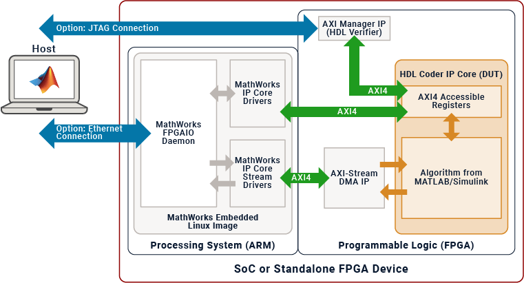
You can use MATLAB FPGA I/O host interface scripts when you generate IP cores in MATLAB or Simulink. If you use Simulink, you can automatically generate these scripts to match your desired connection method to the host, such as Ethernet or JTAG. If you use MATLAB, you must manually construct the FPGA I/O host interface scripts. Use the scripts to enable MATLAB to communicate with the FPGA using a MathWorks® Linux® SoC environment installed on the board, if the board is connected to the host via Ethernet, or directly with the FPGA if the board is connected to the host via JTAG using the AXI Manager IP.
When connecting to the host via JTAG, you can bypass the processor and directly perform read and write operations on the inputs and outputs of the IP core, which is useful for targeting standalone FPGA boards. Host interface scripts eliminate the need to deploy embedded software or drivers on the processor to run and verify your IP core.
You can use MATLAB host interface scripts in the Run and Verify IP Core on Target Hardware stage of the hardware-software co-design process.
For an example about generating and using host interface scripts in Simulink, see Prototype FPGA Design on Hardware with Live Data by Using MATLAB Commands.
For an example that uses host interface scripts in MATLAB, see Generate IP Core from MATLAB for Blinking LEDs on FPGA Board.
To learn how to generate and manage host interface scripts, see Generate and Manage FPGA I/O Host Interface Scripts.
| Strengths | Limitations |
|---|---|
|
|
Simulink Host Interface Model
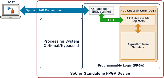
If you are using Simulink to develop your IP core, you can prototype your design on an FPGA platform by using the Simulink host interface model. This method takes advantage of the JTAG AXI Manager IP, which is beneficial when targeting standalone FPGA boards or SoCs that lack a compatible MathWorks Linux image. This method leverages the Simulink environment to interact with the FPGA. By using a Simulink host interface model, you can bypass the processor and directly perform read and write operations on the inputs and outputs of the IP core mapped to the AXI4 registers.
You can use Simulink host interface models in the Run and Verify IP Core on Target Hardware stage of the hardware-software co-design process.
To learn more about creating and using a Simulink host interface model, see Use JTAG AXI Manager to Control HDL Coder Generated IP Core.
| Strengths | Limitations |
|---|---|
|
|
FPGA Data Capture
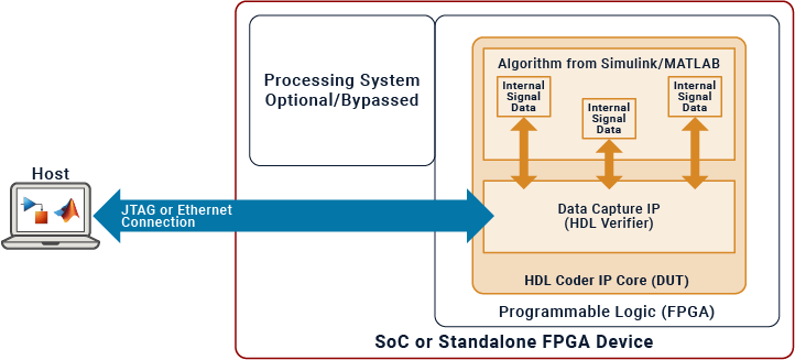
To interface with internal signals within your IP core, you can utilize FPGA data capture. When you develop a model using Simulink, you can automatically integrate this method with your IP core. This method usually involves establishing a JTAG connection to the host. You can employ test points to monitor the internal signals of the IP core while your hardware-software design runs on the hardware. FPGA Data Capture is useful when debugging and analyzing the design of the IP core because it eliminates the need for interface protocol modeling.
You can use FPGA data capture in the Run and Verify IP Core on Target Hardware stage of the hardware-software co-design process.
To learn more about using FPGA Data Capture, see Debug IP Core Using FPGA Data Capture.
| Strengths | Limitations |
|---|---|
|
|
Simulink Software Interface Model in External Mode
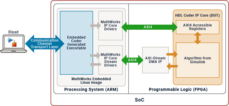
If you are using Simulink to develop your IP core, you can monitor and tune your design by creating a Simulink software interface model and running it in external mode. The Simulink software interface model includes the software portion of the design, which consists of all blocks outside of the HDL DUT subsystem. Software interface models replace the DUT algorithm from your original model with AXI driver blocks based on the target platform interface table and reference design settings. The software interface model interacts with the deployed IP core on the FPGA by using the AXI driver blocks.
Additionally, you can use Embedded Coder to generate C code from your software interface model, build it, and deploy it to the processor. Running your software interface model in external mode establishes automatic communication channels between the host PC and the hardware, which enables parameter tuning and data visualization on the host PC. This functionality allows you to not only run and verify your IP core but also configure the software interface to the FPGA.
You can use Simulink software interface models in these stages of the hardware-software co-design process:
To learn more about monitoring and tuning your design using a Simulink software interface model, see Debug IP Core Using Hardware-Software Deployment.
| Strengths | Limitations |
|---|---|
|
|
Simulink Software Interface Model for Standalone Applications
If you are using Simulink to develop your IP core, you can create a standalone application intended for production-level designs. This approach involves integrating both the HDL DUT subsystem and the software portion of your design in the model. If needed, you can also use UDP Send and UDP Receive blocks to enable external communication. You can use Embedded Coder to compile and deploy a standalone executable of the model onto the processor that is completely independent of any connection to Simulink.
You can use Simulink software interface models for Simulink standalone applications in these stages of the hardware-software co-design process:

For more information about generating a Simulink standalone application, see Build and Run Executable on Xilinx Zynq Platform (Embedded Coder).
| Strengths | Limitations |
|---|---|
|
|
Generic Software Interface
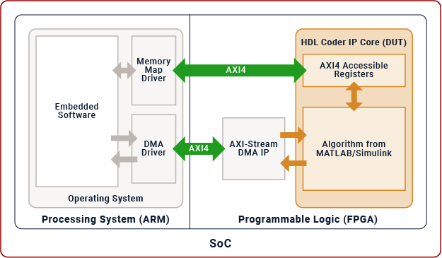
If you have a production-level design, you can use a generic software interface to manually implement embedded software and drivers on the processor using third-party tools. For example, you can write C code to run in bare metal, a real-time operating system (RTOS) or an embedded Linux environment. You can use these software implementations to interact with and control your IP core on the FPGA. Additionally, generic software interfaces are compatible with IP cores generated and deployed with MATLAB or Simulink.
You can use generic software interfaces in the Hardware-Software Deployment stage of the hardware-software co-design process.
To learn more about files generated by HDL Coder during the IP core process, see Custom IP Core Generated Files.
| Strengths | Limitations |
|---|---|
|
|
See Also
Topics
- Generate and Manage FPGA I/O Host Interface Scripts
- Generate Software Interface Model to Probe and Rapidly Prototype HDL IP Core
- Communicate with the Programmable Logic IP Core on AMD Zynq Board by Using AXI4-Lite Protocol (Embedded Coder)
- Communicate with AMD Zynq Boards Using UDP Protocol (Embedded Coder)
- Model Design for AXI4-Stream Interface Generation