AWGN Channel
Section Overview
An AWGN channel adds white Gaussian noise to the signal that passes through it. You can
create an AWGN channel in a model using the comm.AWGNChannel
System object™, the AWGN Channel block, or the awgn function.
The following examples use an AWGN Channel: QPSK Transmitter and Receiver and Estimate Symbol Rate for General QAM Modulation in AWGN Channel.
AWGN Channel Noise Level
Typical quantities used to describe the relative power of noise in an AWGN channel include:
Signal-to-noise ratio (SNR) per sample. SNR is the actual input parameter to the
awgnfunction.Ratio of bit energy to noise power spectral density (Eb/N0). This quantity is used by Bit Error Rate Analysis app and performance evaluation functions in this toolbox.
Ratio of symbol energy to noise power spectral density (Es/N0)
Use the convertSNR
function to convert between these ratios.
Relationship Between Es/N0 and Eb/N0
The relationship in dB between Es/N0 and Eb/N0 is:
where k is the number of information bits per symbol.
In a communications system, the modulation alphabet size and code rate of an error-control code influence k. For example, in a system using a rate 1/2 code and 8-PSK modulation, the number of information bits per symbol (k) is the product of the code rate and the number of coded bits per modulated symbol. Specifically, (1/2)log2(8) = 3/2. In such a system, three information bits correspond to six coded bits, which in turn correspond to two 8-PSK symbols.
Relationship Between Es/N0 and SNR
The relationship in dB between Es/N0 and SNR is:
where Tsym is the symbol period of the signal and Tsamp is the sampling period of the signal. Tsym/Tsamp computes to Samples/Symbol.
You can derive the relationship between Es/N0 and SNR for complex input signals as follows:
where
S = Input signal power, in watts
N = Noise power, in watts
Bn = Noise bandwidth in Hertz = Fs = 1/Tsamp.
Fs = Sampling frequency in Hertz
For a complex baseband signal oversampled by a factor of 4, the Es/N0 exceeds the corresponding SNR by 10log10(4).
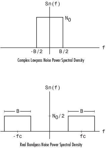
Behavior for Real and Complex Input Signals
These figures illustrate the difference between the real and complex cases by showing the noise power spectral densities of a real bandpass white noise process and its complex lowpass equivalent.