Results for
- Work directly in MATLAB and Simulink Online
- Solve real-world challenges with guidance from MathWorks experts
- Connect with peers across industries
- Ask questions and get live feedback
- Beyond the Labels: Leveraging AI Techniques for Enlightened Product Choices
- A Hands-On Introduction to Reinforcement Learning with MATLAB and Simulink
- Curriculum Development with MATLAB Copilot and Generative AI
- Simscape Battery Workshop
- Generating Tests for your MATLAB code
- Hands-On AI for Smart Appliances: From Sensor Data to Embedded Code
- A Hands-On Introduction to Reduced Order Modeling with MATLAB and Simulink
- Introduction to Research Software and Development with Simulink
- Hack Your Carbon Impact: Build and Publish an Emissions Tracker with MATLAB
- How to Simulate Scalable Cellular and Connectivity Networks: A Hands-On Session

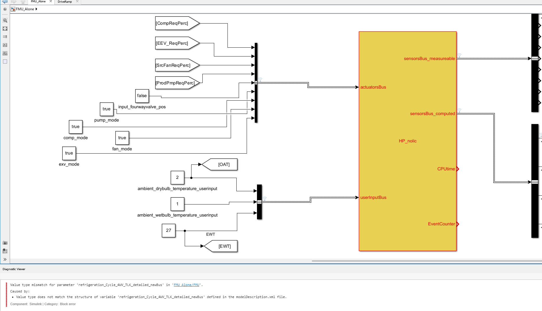
- I open the MQTT Configure block.
- I fill out all the required fields — Broker address, Port, Client ID, Username, and Password.
- When I click Test Connection, it says “Connection established successfully.” So far so good.
- Then I click Apply, close the dialog, set the topic name, and try to run the simulation.
- At this point, I get the following error:Caused by: Invalid value for 'ClientID', 'Username' or 'Password'.
- When I reopen the MQTT config block, I notice that the Password field is empty again — even though I definitely entered it before and the connection test worked earlier.
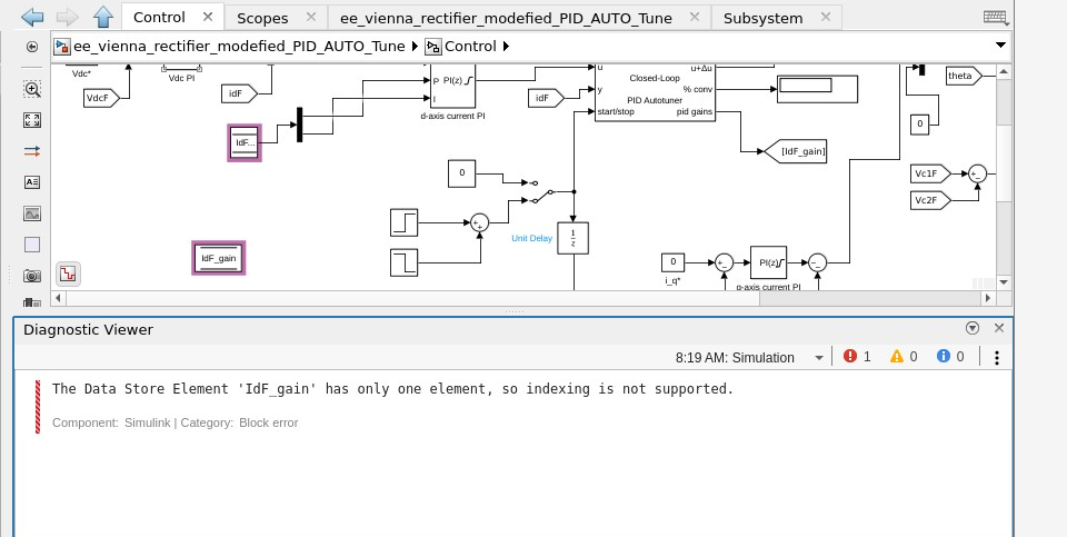
- Can I create a custom PIL target using Embedded Coder?
- Would I need to port rtiostream manually for communication over UART?
- Could I somehow integrate with Keil µVision (which I use for TLE9879) to build and run the generated code?
- Is there a workaround to simulate PIL behavior using a non-supported board?
- Simulink R2024b
- Infineon TLE9879 EVALKIT
- Keil µVision 5 + Infineon Config Wizard
- UART and JTAG interfaces available
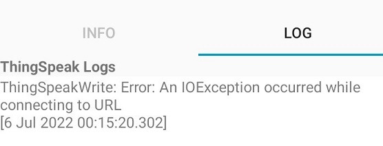
- I'm trying to upload to the server every 3 seconds (which seemed to be providing the best results so far). Since the channel only accepts data transmit every 15 seconds, what is the optimized upload interval rate to match the interval rate of the channel? Because otherwise I have realized that my interval rate can go up to 1min sometimes for some reason.
- Is reading from/writing to the channel through simulink while the system is uploading data to the channel slow down th whole process? What is your overall suggestion in this case?

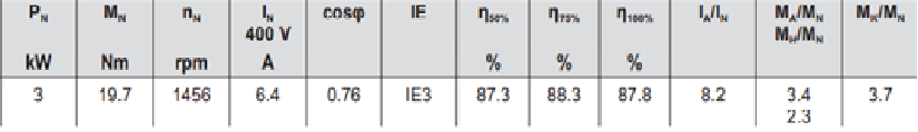
I have a datasheet of an induction motor (as figure below). I want to simulate it on matlab/simulink, but I don't know it's parameters (Lls, Llr, Lm, Rr, Rs).
I tried to search about open circuit test and blocked rotor test to determine these parameters, but some of information doesn't appear on datasheet and I don't have the real motor to test on it (datasheet is only think I have).
Could someone help me with this?
Are you looking for ways to keep your students engaged in a virtual setting? Would you like to spice up your courses with hands-on projects? Using Arduino Engineering Kit, you can achieve these. Due to COVID-19, many instructors started to look for creative ways of giving students a lab experience. Some of them chose to create virtual labs, some of them designed hardware projects with low-cost hardware or integrated hardware projects kits to their curriculum. If you are interested in how Dr. Azadi from San Francisco State University used Arduino Engineering Kit during the pandemic to teach his Mechatronics course, check out these articles:
Hi, I'm trying to send with a serial connection a signal. The signal is just a byte (uint8) that I want to send to my evaluation board every 1 millisecond using Simulink. How can I do that? I tried using the Serial Send block, but the result is different from what I expected to see. Then I tried to use the To instrument block, but I don't know why there isn't the port COM 5 so I couldn't use it.
Prof. Ayse Tekes shares her story on teaching labs remotely with Simscape:
One of the objectives of lab-based instruction can be to develop students’ familiarity with hardware equipment. When students could no longer come to their lab in person, educators at HTW Dresden developed a MATLAB app using App Designer to replicate the controls on lab equipment such as a signal generator and oscilloscope. Read this article to learn more about how Dr. Henker and Dr. Kelber virtualized their electrical engineering labs.
If you use Simulink or Simscape models for your virtual labs, you can create an interactive display of controls and displays within your model diagram using blocks from the Dashboard library. To do so, connect block parameters to control blocks (knobs, buttons, and switches) and signals to displays blocks (scopes and gauges).
New customizable Knob, Vertical Slider, and Horizontal Slider blocks introduced in R2021a let you choose your own background image, foreground image, handle or slider image, and scale appearance. By combining these with custom gauge blocks, you can create intuitive and photo-realistic dashboards for interacting with your models, such as in the image below.
View examples of controlling simulations with interactive displays, or read some more Tips for Moving your Lab-based Classes Online.