Results for
Hi everyone, I'm trying to estimate the Frequency Response of a buck converter. I've found this article: https://it.mathworks.com/company/newsletters/articles/estimating-the-frequency-response-of-a-power-electronics-model.html I've adapted the procedure to a buck converter and followed the instructions but something went wrong. In the last step I've performed a time-domain verification in a Simulink® simulation with the switch-mode buck converter and a Transfer Function block implementing the parametric estimation and compare the response of both systems to the same small perturbation signal but the estimated model response doesn't match the switching model response. I don't know why I've got a diverging systems. I've tried to reduce the load and modify the duty cycle but nothing changed. How can I fix it?

In the link below (File Exchange), you'll find an example with an electric motor supplied by a fuel cell stack (Simscape implementation) and a battery. When motor load is low-to-normal, the fuel cell provides excess energy, that is used to recharge the battery. At motor peak load, the battery needs to contribute in order to complete the expected duty. If you have any query or thoughts, please reach me at jsagardu@mathworks.com
https://www.mathworks.com/matlabcentral/fileexchange/59343-fuel-cell-battery-driven-electric-motor-h2-transfer
Hi All,
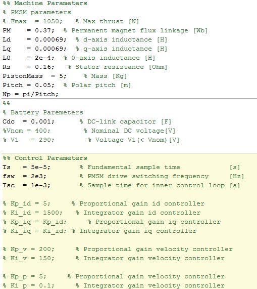
Using the PMLSM SimScape block for my FOC PMLSM model - PMLSM
In the example ee_pmlsm_drive.slx which i have based my FOC architedure on, have a few questions please.
There is a gain block after the outer loop velocity controller (iq_Ref), which is the inverse of the Force constant (Kt) shown as (2/3*Np*PM) in the literature. This is also used in the PMSM FOC model, placed after the torque limiter Tq to iq_Ref. Why is this inverse Kt gain added to the idq_ref signal? Does this cancel Kt if its used in the Force Equation?
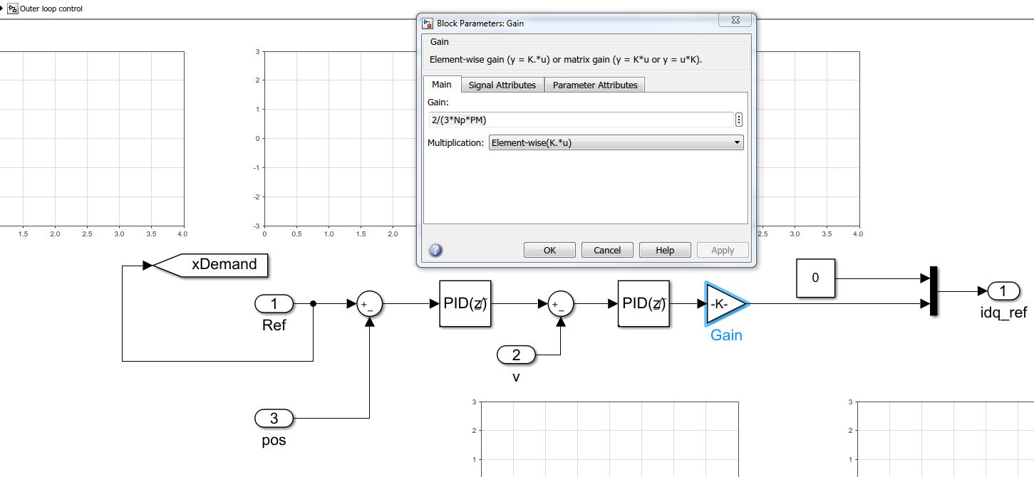
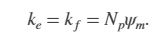
Previous help posts regarding the Force Constant (Kt), imply emitting the constant (3/2) in Kt. Also in the PMLSM help center document states Ke, Kt and Flux linkage are equal. Does this simplification apply to the translational machine counterpart SimScape block?
I have tried to look into the SimScape block code of the PMLSM to confirm, how do i look under the mask to check the Force equation for the PMLSM to confirm Kt and Ke used in this model?
Any help would be great as this is holding up Validation of my "small signal" linear PMLSM model against the SimScape PMLSM block model.
Thanks
Patrick
I'm a student. Please send me a simulation of a residential microgrid. I need this simulation for my university thesis. My thesis is about economically efficient operation of a residential microgrid using the mopso algorithm.
Hi All,
Looking for guidance on how to represent a PMSM 3-Phase Converter (DC bus to AC) as a simply 1st Order Transfer Function in my Simulink model.
Researching this, have found we can show the Power Converter as a simple gain and time delay such as G_inv(s) = K_Inv/(1 + T_inv s)


The gain requires V_cm, which is the control voltage, is this control voltage the "Forward Voltage, Vf" in Switching Devices tab in the block?
Is my assumption for the tf for the converter correct?
Thanks
Patrick
Dear power electronics control community,
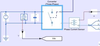
Since I have not solved the problem and have not found an answer to why I receive such an output, I would be happy when you could help me out. The actual project is much more extensive but easy schematic of what I want to do is here:

For that, I am using 2-level PWM generator: https://se.mathworks.com/help/physmod/sps/powersys/ref/pwmgenerator2level.html In the DC-link (DC voltage after the converter) the DC voltage output should be more-less constant (with a little noise) but right now it very far away from the desired output:

Does anyone have a idea what might cause this problem?
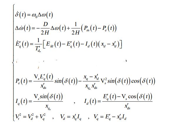
Hi Everyone, I am trying to simulate the third-order model of the synchronous generator (figure below). but I have no idea how to do this. Any help would be great.
Looking to get Solar Grid Tie Inverter developed including Hardware + Software + Enclosure design (IP 65) for single phase inverters from 1 KW to 6 KW.
Hi Everyone,
Require some guidance and pointers on model ee_pmlsm_drive please.
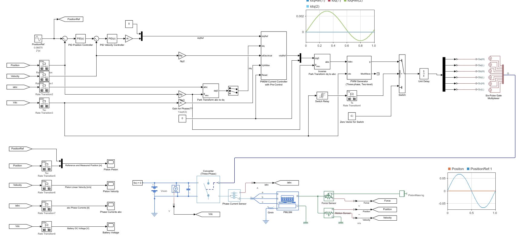
Its regarding a PMSM linear machine model, with a cascade (position and speed) outer loop and a current controller inner loop (Id and Iq currents).
The current Simulink model uses a low voltage DC supply (48v) and uses a step input to the system. My system uses a HV source (400v) and the input is sinusoidal position, with an operating frequency range of 0 to 20hz.
I have used the original model, re-created my own (to learn Simulink/Simscape) with a HV battery source (400v) and used machine parameters that match the application (peer reviewed publication).
As my power electronics background is limited, my background is mechanical, i am unable to tune the inner and outer loops, and am unsure in what order to tune. My project is to use the linear PMSM to drive (motoring) a linear piston for combustion and also use the linear piston to drive the PMSM (generating).
Using the built in PID tuner for the outer speed and position loops i am encountering an error (plant cannot be linearised). I am using a simple 1 hz sine wave to simulate the reference position set-point. With all PID values set to default i have no dq currents, however i have idq ref from the outer velocity controller loop.
Any help with resources and guidance as to how to tune the loops for my updated parameters on this model would be great.
Hi, Currently modelling an reciprocating engine coupled to a linear PMSM motor/generator for my PhD. I have downloaded the "Model File Package for Motor Control Design Public Video" simulink model.
Is it possible to convert to rotational PMSM simscape plant model used for a linear PMSM model? As there are none in the library to just drag into the existing control model.
Any ideas i can represent a linear motor based on this existing control model?
My output from the machine needs to be linear position w.r.t, with a total stroke of approximately 100 mm. Can i convert the rotational constant speed input at port "W" to a sinusoidal velocity profile (such that it replicates the velocity profile of a linear machine)?
Any help would be great.
Thanks
Hello, I want to generate Sinusoidal PWM for 3 level inverter. But I can not finding the way of connect these blocks togather. Is it possible to conenct them? Is there any other way to generate SPWM in simulink?
Hello everyone! I'm trying to find an optimal placement for a recloser using the optimization toolbox. The best place to set a recloser is defined by minimal SAIFI (system average interruption frequency index) value. I've created a little function where Nt - total number of customers, G - are some weights characterizing power lines, Xi - number of interrupted customers (if interruption happens in i-th line AND it has a recloser in it), Mi - row of 1 and 0 (that genetic algorithm should use as a gene I guess...) Here's the code of function:
function [S] = SAIFI_sum (M)
Nt=270;
G = [1.1 1.2 1.3 1.4 1.5 1.6];
X = [270 30 220 180 60 70];
  for i=1:length(M)
      if  M(i)== 1
      N(i) = X(i);
  else
          N(i) = Nt;
      end
  end
  S = 0;
  for j=1:length(M)
      SAIFI(j) = N(j)*G(j);
      S = S + SAIFI(j);
  end
   S
end
As a result I have 51 same results: S = 297 and following message:
"Optimization running.
Objective function value: 297.0
Optimization terminated: average change in the fitness value less than options.FunctionTolerance".
I couldn't understand how to solve this problem.

Hello friends i have strugled to develope codes in matlab and spent ample time in converting the available codes to my area . If any of the researcher are interested to share their codes with me are welcomed and collabarations are welcomed ...currenty i need a basic code in unit commitment using real coded and binary coded for Security contrained and integrating Reneweable energy .. I too will share my codes because world is going to vanish soon so my knowledge should spread across the globe
with rds s.praveen kumar email:praveenaups777@gmail.com
Check out this short video on the new features in Simulink R2020a . What's your favorite new feature?
Just wanted to post a link to this video we recently published on YouTube:
PID Controller tuning for a buck converter
Let me know what you think. Arkadiy
Hi everyone,
I am trying to control an actuator with brushless DC Motor in Simulink. At one point, I am in need of the motor rotation and the only parameter available to me is the duty cycle and the direction of rotor. I knew that it is not possible to calculate rotation from duty cycle. In case if some one have idea about this or some suggestions, could you please share with me
Thanks in advance
Hello,
I am trying to simulate a PMSM, which has a Quasi sinusoidal back-emf waveform. Is there any way I can define the back emf to be anything other than Sinusoidal/Trapezoidal?
Thanks in advance. Saurabh Kumar
Recently, I have been learning the mathematical modeling of switching converters. Looking for a lot of data, I know that the current loop control mainly includes peak current, valley current and average current control methods. The detailed process of peak current modeling is found in the book "modeling, control and digital realization of switch converter". However, my brother has not found the detailed introduction of average current modeling. I would like to ask you brother and sister have any good information recommendation, the best is books (the most detailed explanation). Thank you very much!
I have issue with the design that i have downloaded from mathwork community. how to solve regarding this matter
Failed to load library 'powerlib_models' referenced by 'mcupqc/Subsystem/Voltage Measurement/model' Component:Simulink | Category:Model error Failed to load library 'powerlib_models' referenced by 'mcupqc/Three-Phase V-I Measurement/model' Component:Simulink | Category:Model error Failed to load library 'powerlib_models' referenced by 'mcupqc/Three-Phase V-I Measurement1/model' Component:Simulink | Category:Model error Failed to load library 'powerlib_models' referenced by 'mcupqc/Three-Phase V-I Measurement2/model' Component:Simulink | Category:Model error Failed to load library 'powerlib_models' referenced by 'mcupqc/Three-Phase V-I Measurement3/model' Component:Simulink | Category:Model error Failed to load library 'powerlib_models' referenced by 'mcupqc/Three-Phase V-I Measurement4/model' Component:Simulink | Category:Model error Failed to load library 'powerlib_models' referenced by 'mcupqc/Three-Phase V-I Measurement5/model' Component:Simulink | Category:Model error Failed to load library 'powerlib_models' referenced by 'mcupqc/Three-Phase V-I Measurement6/model' Component:Simulink | Category:Model error
Hello everyone, I am trying to implement 3 level space vector modulation for a multilevel inverter. Without mapping vector for region selection of three level space vector, I am getting reference angle started from sector-1 to sector-6 as shown in ''theta_ref'' file. But when I am implementing mapping references for region selection (please see in the attached file ''mapping_reference''), the reference angle is shifting 180 degree that means it is starting from sector-6 to sector-1 as in attached file ''theta_ref_with_region_identification''. Could anyone please let me know why this is happening and how to solve this problem?
Thanks in advance.