Results for
I have a datasheet of an induction motor (as figure below). I want to simulate it on matlab/simulink, but I don't know it's parameters (Lls, Llr, Lm, Rr, Rs).
I tried to search about open circuit test and blocked rotor test to determine these parameters, but some of information doesn't appear on datasheet and I don't have the real motor to test on it (datasheet is only think I have).
Could someone help me with this?
I need to model a brushless motor for which I only have the data of voltage, power, speed, nominal torque, starting torque, max current and total weight, which moves a bicycle. I have studied the Permanent Magnet Synchronous Machine power_pmmotor Simulink example, but I do not have all the required data. My question is whether it is possible to make an approximate model with my few data. I guess some data could be assumed, but I don't know what typical values would be correct. I would greatly appreciate any suggestion. My best regards.
Hi,
I am new to Matlab and looking to model complete EPS system starting with battery modelling. I have seen videos where the modelling is explained but looking for a one which can teach me from the scratch.
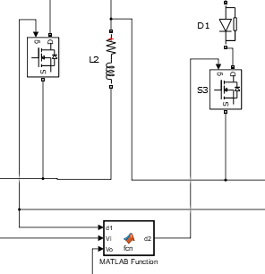
Hi, currently I'm studying about DC-DC Boost converter with controller. After I applied the step time, the output voltage supposed to follow the step time, but there is some delay in the simulation results after I applied the "step time" in the step input block. Can someone help, why this delay occur? Please see the attached pictures. Thanks
As per data sheet for VIPER22A, the product is obsolete.
For UC3843A you will have to refer to the data sheet, link given below: https://www.ti.com/lit/ds/symlink/uc3843a.pdf?ts=1637624394197&ref_url=https%253A%252F%252Fwww.ti.com%252Fproduct%252FUC3843A
For UC3843A, the reference output voltage is 5 V and the normal output voltage is 13.5 V.
After repairing the power supply of a big water buffalo PC150NCA, now all the parts found to be broken are replaced, but the power-on output 12V is only 4.2V. The original power supply block is UC3843B, which is not sold locally. I can only buy a UC3843A replacement . I don’t know if the low output voltage has anything to do with this (the optocoupler and the 431 voltage regulator block have also been replaced)
With the switching power supply made by VIPER22A scheme , the 5V output always has noise, and the ripple exceeds 200MV after loading. How to change it? 1. 220VAC input, two outputs, 24V and 5V output are noisy, the ripple after 5V load is more than 200MV, 5V is connected with an LDO to 3.3V, and the measured 3.3V is also noisy, and the LDO heats up seriously. Change The LDO remains unchanged. 2. It is suspected that the load current is large, but I changed a circuit board with the same scheme and found that there is no noise. Although there are ripples, it is not very hot. 3. In addition, directly use a 5V adapter to convert to 3.3V through the same LDO. problem. How to change the device in this figure? 4. For hardware novices, the transformer will not be changed temporarily, and I hope to improve it by adjusting other devices.
Hello! I am a 3rd year mechanical engineering student from IIT Ropar. We are participating in EBAJA 2022. I thank Mathworks for providing the customisable vehicle template https://www.mathworks.com/matlabcentral/fileexchange/79484-simscape-vehicle-templates
I have learnt to customise the models parameters of Bus, Sedan, Trucks, etc using the UI provided. However the vehicle models does not include the BAJA ATV in it which we required the most for the animations and simulation results. I needed some assistance for replacing the given vehicle model with a BAJA ATV.
-Tushar Raut LinkedIn: https://www.linkedin.com/in/tushar-raut-73ba75194/
My simulink program require a feedback loop from an AC signal. How does one create a mean/ median value from a sinusoidal signal. Specifically, I want to average a power signal for last 0.1 sec and then adjust PWM signal.
I am trying to simulate the PMSM in fault mode with phase loss at 0.25 sec, but the simulation results are incorrect. For example, the rotor speed changes too much when a phase is missing. I tried to assemble the model in dq coordinates and abc coordinates on my own, but the results are the same. Who can tell you how to modify the engine model so that the simulation shows the correct results?
hi everyone could you explain to me why the three phase voltages in this video are not sinusoïdale and how to change them To be sinusoidale?
Youtube video: Motor Control Design with MATLAB and Simulink
link:https://www.youtube.com/watchv=lP4jbmthiyc&t=1103s&ab_channel=MATLAB
why does this work?
Hi All,
Quick question regarding deriving PM flux linkage [Wb] from a torque constant estimated from data on a PMLSM.
I have an estimated torque constant Kt [N/A], which is from experimental test data. I will now parameterising my Simscape PMLSM block from this torque constant.
The literature seems confusing, to derive PM flux linkage [Wb] from the experimental torque contant do i include the (3/2) constant. Some examples include the constant and some omit, which one of the following is preferred for deriving the PM flux linkage?
Thanks
Patrick
MathWorks is please to offer a new training course, Power Electronics Control Design with Simulink and Simscape.
This one-day course focuses on modeling and controlling power electronic systems in the Simulink® environment using Simscape Electrical™. Topics include:
- Modeling direct current (dc) power electronic components
- Controlling the level of fidelity in a model
- Developing controls for power electronics
- Modeling three-phase alternating current (ac) power electronic components
- Controlling power electronics for motor drive applications
Hi everyone,
I am a third year BEng Energy Engineering student. I am looking at the design, modelling and peformance of an HVDC power converter for use in offshore wind for my final year dissertation. Power electronics is a new area for me and I am also new to simulink/ simscape elctrical.
Could anyone provide some useful examples of MMC (in particular rectifiers), or some advice for designing in simscape electrical. I am struggling with the design of PWM control especially. I aim to make a scaled down version of the MMC in Simulink but so far have had no luck. If anyone can help I would be really appreciative.
Thanks in advance.
Joe
Hi everybody!I've realized a DC/DC Buck Converter Model with closed loop control system. I need to limit the overshoot in the step response of the submitted system. I've already tried to tune the controller in the PID Tuner by manually adjusting the overshoot by moving the response time slider, as it is said in this article: https://it.mathworks.com/help/slcontrol/gs/automated-tuning-of-simulink-pid-controller-block.html The problem is that it is not accurate. I manage to get an overshoot of 4.77% or 5.4%, whereas i need to set the parameters in order that the overshoot is 5%. Should I use TuningGoal.Overshoot? How am I supposed to do? How should I set the input and output in my model? I've read Matlab documentation but I didn't catch that. Thanks in advance!
Please I would be glad if I could be helped with the design of Microturbine coupled with PMSG.