NR Polar Decoder
Perform polar decoding according to 5G NR standard
Libraries:
Wireless HDL Toolbox /
Error Detection and Correction
Description
The NR Polar Decoder block implements a streaming polar decoder with hardware-friendly control signals. The 5G NR standard uses polar codes for channel coding of the DCI, UCI, and BCH transmit channels.
You must specify the link direction because the coding scheme defined by the 5G NR standard is different for downlink and uplink messages. Downlink messages are encoded with interleaving and use a CRC length of 24 bits. Uplink messages do not use interleaving, and use a CRC length of 6 or 11.
This block implements a CRC-aided successive-cancellation list decoder. This
implementation matches the performance of the nrPolarDecode (5G Toolbox) function. You can
choose a list length of 2, 4, or 8. Increasing the list length increases the error correction
performance but uses more hardware resources and increases the decoding latency. You can
improve decoding performance for DCI messages by using the optional RNTI
port to specify an expected RNTI value.
This block also performs CRC decoding of the message, equivalent to the nrCRCDecode (5G Toolbox) function. The block selects the CRC length based on your
specification of the link direction and the K value you provide. The
block detects DCI messages from the values of K and
E, and automatically prepends 1s to the message, equivalent to the
padCRC input argument of the nrPolarDecode (5G Toolbox) function.
Because the latency of the polar decoding operation can vary, the block provides an output signal, nextFrame, that indicates when the block is ready to accept new inputs. For more details, see the Latency section of this page.
Examples

Polar Encode and Decode of Streaming Samples
Simulate NR Polar Encode and Decode blocks and compare the hardware-optimized results with results from 5G Toolbox™ functions.
Ports
Input
Output
Parameters
Algorithms
This block implements a CRC-aided successive-cancellation list decoder. It can use a list
length of 2, 4, or 8 as configured by the List length parameter. The
decoder iterates over all LLRs in the tree to reach a decision for a bit and then uses that
decision to decode the next bit. The deinterleaving step is included only when you set the
Link direction parameter to Downlink.
This diagram shows the architecture of the polar decoder.
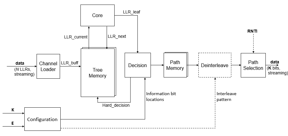
The block uses the Configuration stage when the K and
E input port values change. The block computes the locations of the
information bits and passes them to the Decision stage. Because the mapping patterns are
computed as needed, rather than stored in hardware, the block supports all
K and E values within the supported range. The
Configuration stage also computes the interleave pattern when you set the Link
direction parameter to Downlink.
When you set the Configuration source parameter to
Property, the K and E
values are constants, so the decoder does not implement the Configuration stage. In this case,
the block includes static lookup tables that contain the precomputed configuration.
To minimize computations for each decode, the Tree Memory stores the probability of each node being a one or a zero. Each iteration updates only the LLRs that have changed. The Core decoding stage uses the LLR update equations from [3].
The Decision stage checks the LLR value against the expected locations of information bits and frozen bits and returns a hard decision to the Tree Memory. If the bit is expected to be frozen, the Decision stage returns a hard decision of zero and updates the probabilities of related paths. The Path Memory reconstructs the most likely paths from the hard decision results and passes the paths and scores to the next stage.
Tree Memory and Path Memory contain up to List length paths. If all frozen bits on a path are zeros (as expected), then the block discards the other parallel paths. This optimization results in variable latency in the decoding operation for list lengths greater than two. For signals with a high noise level, the decoder must increase the number of parallel paths and the cycles for decoding. For low-noise signals, the decoder can use only two parallel paths and reduce the decoding latency.
The Path Selection stage computes the CRC for all paths and then chooses the path that passes the CRC. When you use the RNTI input port, the block compares the internal CRC checksum with the target RNTI value. Otherwise, the block compares the CRC checksum against a value of 0. If all CRCs fail, the block returns the path that has the higher score.
This implementation matches the performance of the 5G Toolbox™ function nrPolarDecode (5G Toolbox) with the same list
length. Because the block uses fixed-point internal types, any differences are a result of
quantization.
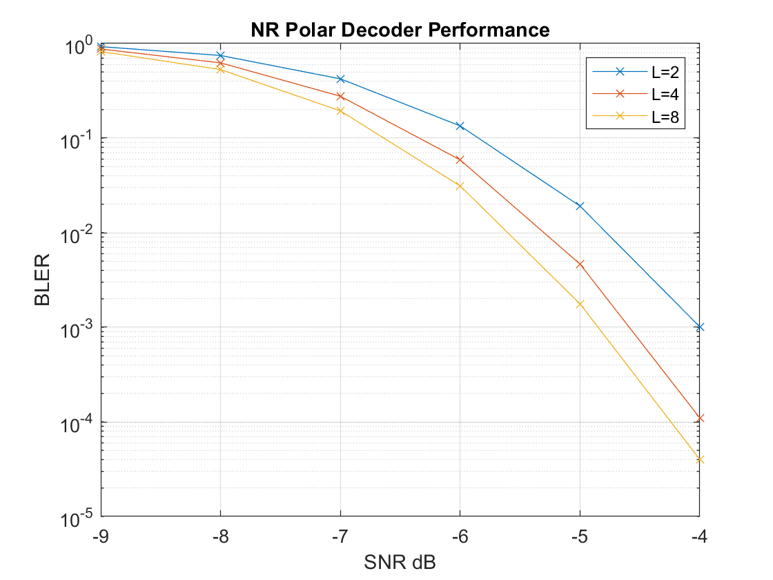
This plot shows the block error rate performance with the three possible list lengths. The input is 6-bit LLR values.
The table shows example latencies of the NR Polar Decoder block for each N, when decoding for uplink and downlink channels with a list length of two. N is the power-of-two encoded message length determined from the values of K and E.
| N | Uplink Latency | Downlink Latency |
|---|---|---|
| 32 | 349 | Not applicable |
| 64 | 576 | 677 |
| 128 | 1034 | 1135 |
| 256 | 1961 | 2062 |
| 512 | 3896 | 3996 |
| 1024 | 8202 | Not applicable |
The exact latency varies based on the values of K and E. The latency is longer for frames where the K and E input port values change and the block must compute the new configuration.
Increasing the list length increases the latency. List lengths greater than two do not have a fixed latency for given K and E values. To provide minimal latency, the block traces more than 2 paths only when the frozen bits are not decoded as zeroes. This optimization means that the latency can increase with the SNR of the input signal. For example, for a list length of 4 and N=512, the best case latency is 4108 cycles, and the worst case latency is 4985 cycles.
Because the latency varies, use the output nextFrame control signal to determine when the block is ready for a new input frame.
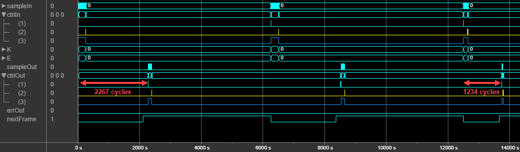
This waveform shows how the latency varies with the K and E input port values for a list length of two. When the input K and E port values are 132 and 256, the block has a latency of 2272 cycles from the input start signal to the output nextFrame. When the K and E port values change to 54 and 124, the latency changes to 1234 cycles.
This waveform shows how the latency can vary with the noise level of the input signal
when using a list length of 4. The block has K and
E parameter values of 132 and 256 and Link
direction parameter set to Uplink. The first message
has a latency of 2533 cycles. This message data is generated with low noise and has few bit
errors. In this case, the decoder can collapse to two paths and produce a result in fewer
cycles than when decoding a noisier signal. The second message is generated with a high
noise level, and the decoding latency increases to 3174 cycles. When the input signal has
more bit errors, the decoder must trace more paths to determine the correct bits.

References
[1] 3GPP TS 38.212. "NR; Physical channels and modulation." 3rd Generation Partnership Project; Technical Specification Group Radio Access Network. URL: https://www.3gpp.org.
[2] Arikan, Erdal. "Channel Polarization: A Method for Constructing Capacity-Achieving Codes for Symmetric Binary-Input Memoryless Channels." IEEE Transactions on Information Theory 55, no. 7 (July 2009): 3051–73. https://doi.org/10.1109/TIT.2009.2021379.
[3] Balatsoukas-Stimming, Alexios, Mani Bastani Parizi, and Andreas Burg. "LLR-Based Successive Cancellation List Decoding of Polar Codes." IEEE Transactions on Signal Processing 63, no. 19 (October 2015): 5165–79. https://doi.org/10.1109/TSP.2015.2439211.
Extended Capabilities
Version History
Introduced in R2020a
See Also
nrPolarDecode (5G Toolbox) | NR Polar Encoder