LTE CRC Encoder
Generate checksum and append to input sample stream
Libraries:
Wireless HDL Toolbox /
Error Detection and Correction
Description
The LTE CRC Encoder block calculates and appends a cyclic redundancy check (CRC) checksum for each frame of streaming data samples. You can select from the polynomials specified by LTE standard TS 36.212 [1]. The block provides a hardware-optimized architecture and interface.
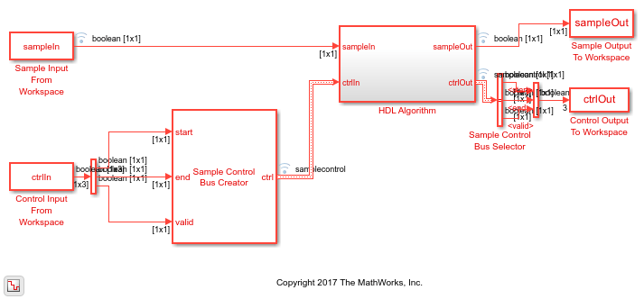
This block uses a
streaming sample interface with a bus for related control signals. This interface enables the
block to operate independently of frame size, and to connect easily with other Wireless HDL Toolbox™ blocks. The block accepts and returns a value representing a single sample, and a
bus containing three control signals. These signals indicate the validity of each sample and the
boundaries of the frame. To convert a matrix into a sample stream and these control signals, use
the Frame To Samples block
or the whdlFramesToSamples
function. For a full description of the interface, see Streaming Sample Interface.
You must not apply another frame before the previous frame has completed. The
hardware-friendly algorithm adds (CRCLength +
3)/InputSize cycles of latency. To account for the
additional cycles of the appended checksum samples, and the latency, you must apply a
minimum spacing of (2*CRCLength +
3)/InputSize between input frames. Alternatively,
you can use the output signal ctrl.end to
determine when the block is ready for new input. If you apply the next frame too early,
the ctrl.start signal resets the checksum
calculation and truncates the previous frame.
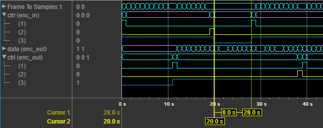
This waveform shows a 40-sample frame, input two samples at a time to a CRC16 encoder.
The gap between the input frames is therefore 8 cycles. Due to the insertion of the
checksum, the output ctrl.valid signal stays
continuously high with no gaps between frames. The input and output
ctrl buses are expanded to show the control signals.
start and end show the frame boundaries, and
valid qualifies the data samples.
Examples
Append CRC Checksum to Streaming Data
Use LTE CRC Encoder block to encode data, and how to compare hardware-friendly design with results from LTE Toolbox™.
Ports
Input
Output
Parameters
Algorithms
When you use vector or integer input, the block implements a parallel CRC algorithm [2]. The implementation is the same as the algorithm used by the Communications Toolbox™ blocks General CRC Generator HDL Optimized and General CRC Syndrome Detector HDL Optimized.
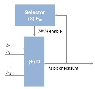
To provide high throughput for modern communications systems, the block implements the CRC algorithm with a parallel architecture. This architecture recursively calculates M bits of a CRC checksum for each W input bits. At the end of the frame, the final checksum result is appended to the message. For a polynomial length of M, the recursive checksum calculation for W bits in parallel is
FW is an M-by-M matrix that selects elements of the current state for the polynomial calculation with the new input bits. D is an M-element vector that provides the new input bits, ordered in relation to the generator polynomial and padded with zeros. The block implements the (×) with logical AND and (+) with logical XOR.
References
[1] 3GPP TS 36.212. "Multiplexing and channel coding." 3rd Generation Partnership Project; Technical Specification Group Radio Access Network; Evolved Universal Terrestrial Radio Access (E-UTRA). URL: https://www.3gpp.org.
[2] Campobello, Giuseppe, Giuseppe Patane, and Marco Russo. "Parallel CRC Realization." IEEE Transactions on Computers. Vol. 52, No. 10, October 2003, pp. 1312–1319.
Extended Capabilities
Version History
Introduced in R2017b