Deploy Frame-Based Optical Flow Algorithm on FPGA
This example shows how to use frame-to-sample optimization from HDL Coder™ in Simulink® to generate and deploy a sample-based optical flow IP core to hardware, and verify it using live streaming data from MATLAB®.
This example is an extension of the Generate HDL Code from Frame-Based Models by Using Neighborhood Modeling Methods (HDL Coder) example and explains the steps involved in generating a bitstream and deploying the design. In this example, you:
Simulate and verify a frame-based design for optical flow that uses the Lucas-Kanade (LK) method and supports HDL code generation.
Generate an HDL IP core that implements a sample-based algorithm, includes a frame buffer, and has AXI4-Stream interfaces.
Integrate the generated IP core into a reference design.
Run the design and process live data on hardware by calling a MATLAB script.
Prerequisites
This example requires: * AMD® Vivado® Design Suite. For supported versions, see the HDL Language Support and Supported Third-Party Tools and Hardware (HDL Coder). * A System-on-Chip (SoC) board. This example uses the AMD Zynq® ZC706 Evaluation Kit.
This example uses HDL Coder Support Package for AMD FPGA and SoC Devices for bitstream generation. To run the example on hardware, you must run the guided hardware setup included in the support package installation.
On the MATLAB toolstrip, in the Environment section, click Add-Ons > Manage Add-Ons.
Locate HDL Coder Support Package for AMD FPGA and SoC Devices, and click Setup.
The setup tool configures the target board and host machine, confirms that the target starts correctly, and verifies host-target communication. For more information, see Guided Hardware Setup for AMD Boards (HDL Coder).
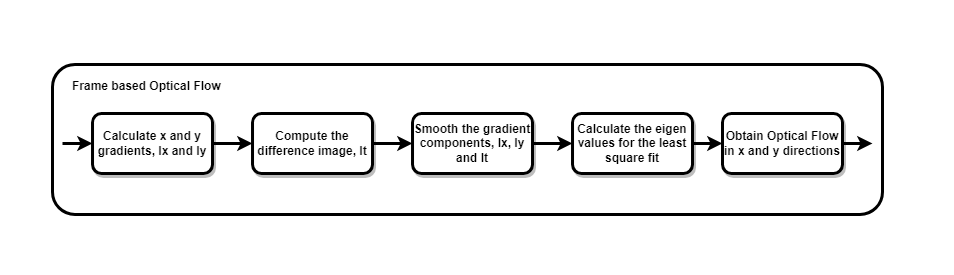
Lucas-Kanade Method
To solve the optical flow constraint equation for u and v, the Lucas-Kanade method divides the original image into smaller sections and assumes a constant velocity in each section. Then it performs a weighted least-square fit of the optical flow constraint equation to a constant model for all the sections in the image. For more information, see the opticalFlowLK (Computer Vision Toolbox) object.
Simulate and Verify LK Algorithm
The figure shows the top-level model. The model includes a video source, the LK algorithm, and a visualization of the output results.
open_system("hdlFrameOpticalFlowExtMemory");
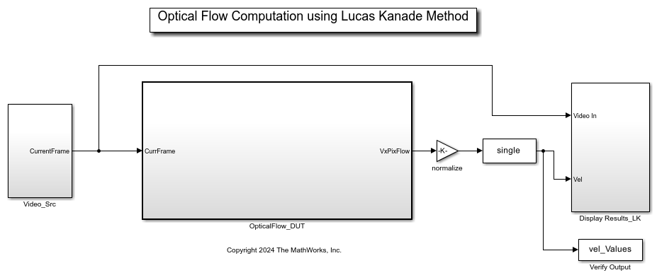
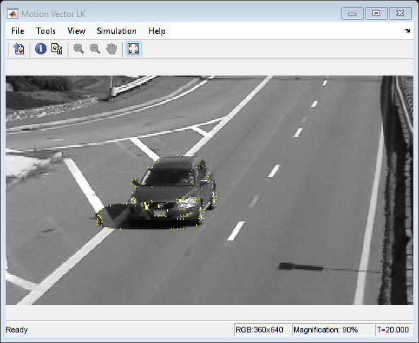
The DUT splits the input video into a previous frame and current frame by using a Unit Delay block. The input signal is a frame composed of 360-by-640 pixels. The hardware reference design supports a maximum bitwidth of 16, so the model casts the pixel values to the int16 data type. When you simulate the model, it displays the optical flow values overlaid on the input frame.
sim("hdlFrameOpticalFlowExtMemory");
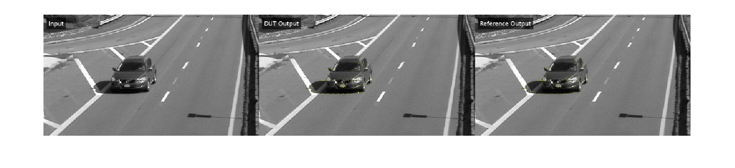
The helperVerifyOpticalFlowDUT script validates the output frames from the model. The script calculates the structural similarity index measure (SSIM) for the output frames against a MATLAB reference and verifies that the SSIM exceeds the minimum threshold. The script calculates the reference image by using the estimateFlow function of the opticalFlowLK (Computer Vision Toolbox) object. The script displays the input frame, reference output, and DUT output.
run("helperVerifyOpticalFlowDUT.m");
Generate and Integrate HDL IP Core
To generate HDL code that includes the hardware interfaces for the deployed design, use the HDL Workflow Advisor tool.
The optical flow algorithm requires calculating a disparity image by subtracting the current frame from the previous frame. This requirement means the design must store the previous frame locally. HDL code generation produces sample-based HDL code from the frame-based OpticalFlow_DUT subsystem. The Unit Delay block becomes a transfer to external memory if the frame size is larger than the DelaySizeThreshold parameter. In this example, DelaySizeThreshold is 100 kilobytes and the frame size is 360-by-640 uint8 pixels, or 230.4 kB. For more information, see Offload Large Delays from Frame-Based Models to External Memory (HDL Coder).

To start the targeting workflow, right-click the OpticalFlow_DUT subsystem and in the HDL Coder app section, click the HDL Workflow Advisor button.
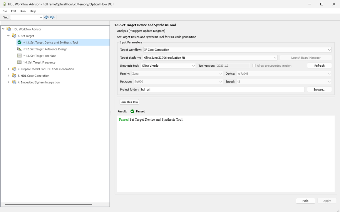
In step 1.1, set Target workflow to
IP Core Generationand Target platform toXilinx Zynq ZC706 Evaluation Kit.
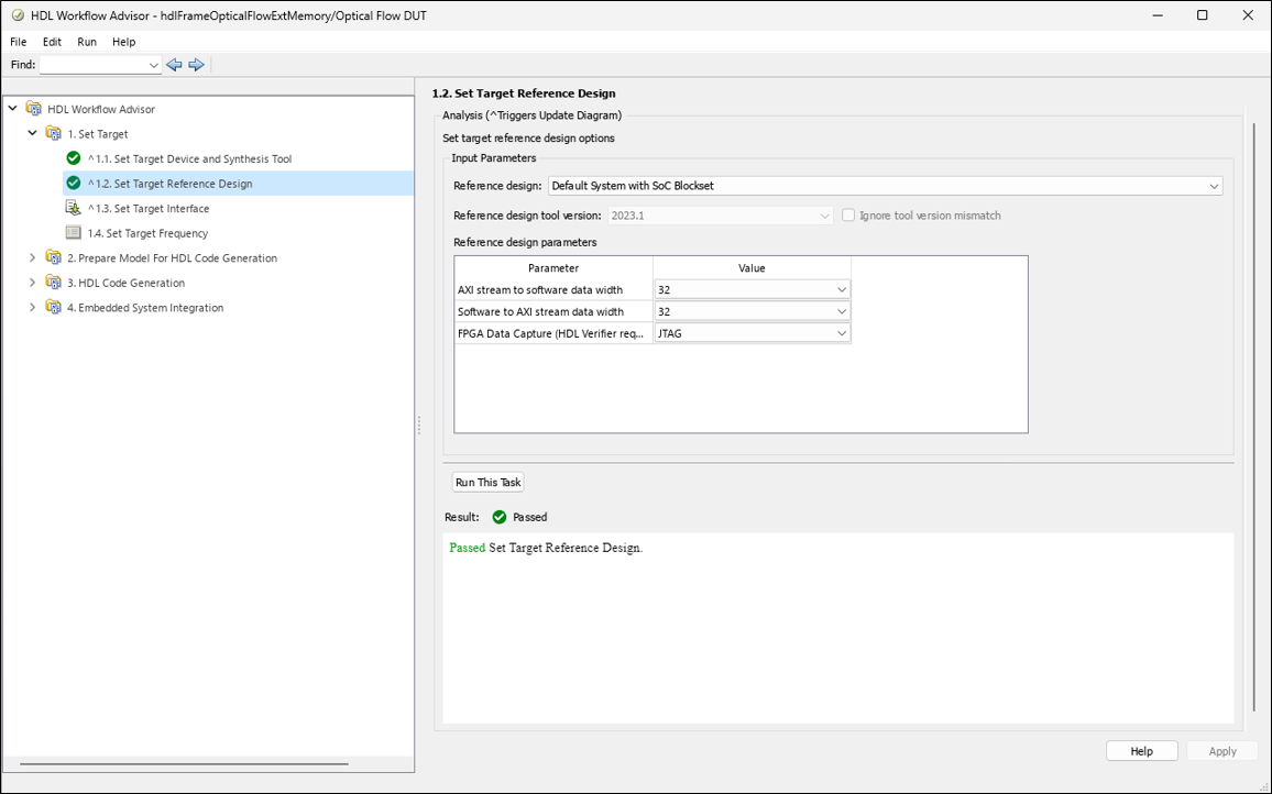
In step 1.2, set Reference design to
Default System with External DDR3 Memory Access.
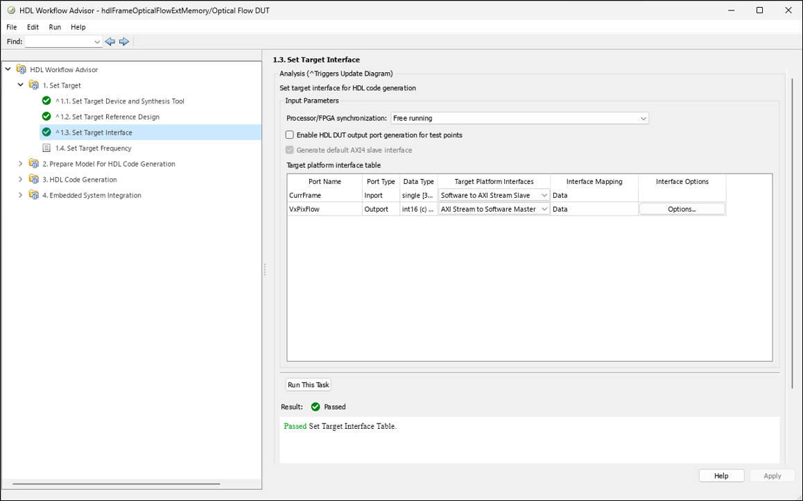
In step 1.3, map the input and output video interfaces of the IP core to AXI4-Stream interfaces.
In step 1.4, set the target frequency for the design to 150 MHz.
Run step 2 to prepare the design for HDL code generation.
Run step 3 to generate HDL code for the IP core.
Run step 4.1 to integrate the newly generated IP core into the reference design.
Run step 4.2 to generate host interface artifacts. This example uses the interface script, and not the software interface model, so you can uncheck Generate Simulink software interface model.
Run step 4.3 to generate the bitstream file. The bitstream file is named
system_wrapper.bitand located athdl_prj\vivado_ip_prj\vivado_prj.runs\impl_1.Run step 4.4 to package and download the bitstream to the FPGA.
After the bitstream is generated, to deploy the bitstream again for subsequent runs, you can open the HDL Code tab and select Build Bitstream > Program Target Device. As an alternative to step 4.3, you can generate a new bitstream by clicking on Build Bitstream in the HDL Code tab. This action generates the bitstream in a shell window outside of MATLAB.
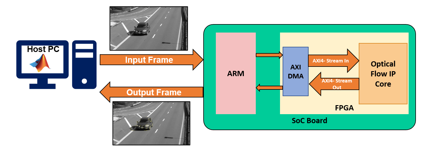
You can interact with the FPGA design by reading and writing data from MATLAB on the host computer as described in the Interact with FPGA Design from Host Computer section of the Prototype Generated IP Core on Hardware using FPGA I/O (HDL Coder) example. The host computer sends and receives frames of data from the board as shown in the high level architecture of the system.
Run Optical Flow System on FPGA
Set up the interfaces for the vision processing system by using the gs_hdlFrameOpticalFlowExtMemory_setup function generated in step 4.2. The function creates AXI4-Stream interfaces for communication between MATLAB and the DUT. The function configures the interfaces for the resolution of the input visiontraffic_cropped.avi video. The DeployFrameBasedOpticalFlow script, shown below, sends and receives video with the DUT by using the AXI4-Stream interfaces and processes the output video.
%% Create fpga object
hProcessor = xilinxsoc();
hFPGA = fpga(hProcessor);
%% Setup fpga object
gs_hdlFrameOpticalFlowExtMemory_setup(hFPGA);
%% Create 5-pixel-wide grid for overlaying the optical flow on the input frame.
v = VideoReader('visiontraffic_cropped.avi');
inputFrame = v.readFrame;
borderOffset   = 5;
decimFactorRow = 5;
decimFactorCol = 5;
[R, C, ~] = size(inputFrame);
RV = borderOffset:decimFactorRow:(R-borderOffset);
CV = borderOffset:decimFactorCol:(C-borderOffset);
[Y, X] = meshgrid(CV,RV);
scaleFactor = 1/255;
%% Process frames from visiontraffic_cropped.avi
% Create figure for display
figure("Name", "Optical Flow Output from Hardware");
% Reset the DUT before writing the first frame
writePort(hFPGA, 'CurrFrame', zeros(size(v.read(1),1:2)));
for ii=1:20
    frameIn = v.read(ii);
    frameInGray = single(rgb2gray(frameIn));
     % Normalize the frame
     frameInGray = frameInGray*scaleFactor;
% Send input frame to Optical Flow IP using hFPGA object.
writePort(hFPGA, 'CurrFrame', frameInGray); % Read output from hardware using hFPGA object.
vel_Values = readPort(hFPGA, 'VxPixFlow'); % Create optical flow lines from the real and imag parts of the data.
tmp = vel_Values(RV,CV);
vel_Lines = [Y(:), X(:), Y(:)+double(real(tmp(:)))*scaleFactor, X(:)+double(imag(tmp(:)))*scaleFactor];
frameOut = insertShape(frameInGray,"line",vel_Lines,"ShapeColor","yellow");
imshow(frameOut);
endWhen you finish working with the example, run this command to release any hardware resources used by the fpga object:
release(hFPGA);