Offload Large Delays from Frame-Based Models to External Memory
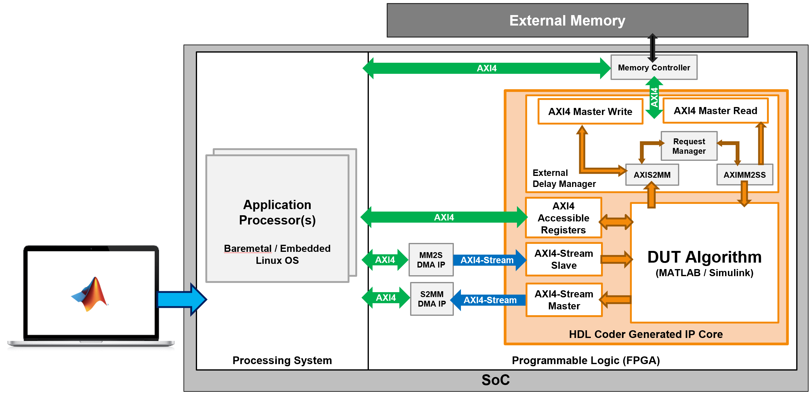
Frame-based algorithms often require storing large amounts of data in external memory for future processing. When you use the frame-to-sample conversion, HDL Coder™ transforms your frame-based algorithm into sample-based HDL code and generates additional ports to offload the delays that the design needs for pipeline computations. During the IP core generation, HDL Coder can map these ports to an AXI4 Master interface to store the data in external memory.

Offloading a large delay is also useful in signal processing algorithms that require a large amount of data to process the input signal. A common image processing application is histogram equalization, which requires building a histogram from an entire input frame in order to equalize the image. This example shows how to leverage the frame-to-sample optimization to generate a sample-based IP core with AXI4-Stream interfaces from a frame-based histogram equalization model.
To run this example, you must have the following software and hardware boards:
HDL Coder Support Package for AMD® FPGA and SoC Devices.
Xilinx® Vivado®. To view the supported versions, see HDL Language Support and Supported Third-Party Tools and Hardware.
Xilinx Zynq® ZC706 Evaluation Kit.
Model a Histogram Equalization Algorithm Using Iterative Operations
Open the HistogramEq MATLAB Function block in the hdlFrame_Zynq_Histogram/DUT subsystem to see the histogram equalization algorithm.
load_system('hdlFrame_Zynq_Histogram')
open_system('hdlFrame_Zynq_Histogram/DUT/HistogramEq')
function im_out = histeq(im_gray)

% Histogram calculation
hist = zeros(1, 256, 'uint16');
hist = hdl.iteratorfun(@hist_kernel_fcn, im_gray, hist);

[row,col] = size(im_gray);
factor = coder.const(fi(255/(row*col)));

% Cumulative distribution function calculation
cdf_init = zeros(1,256,'uint8');
cdf = hdl.iteratorfun(@cdf_compute, hist, cdf_init, factor);

% Equalize input frame: replace the value from look up table
im_out = hdl.npufun(@table_lookup, [1,1], im_gray, 'NonSampleInput', cdf);

end

function count = hist_kernel_fcn(pix, count, idx) %#ok<INUSD>

count(pix+1) = count(pix+1) +1;

end

function cdf = cdf_compute(hist, cdf, idx, factor)

if idx > 1
    cdf(idx) = uint8(cdf(idx-cast(1,'like',idx)) + hist*factor);
else
    cdf(1) = uint8(hist*factor);
end

end

function out = table_lookup(in, cdf)
    out = cdf(in);
end
In the hdlFrame_Zynq_Histogram model, there is a single MATLAB Function block inside the device under test (DUT) that uses the hdl.iteratorfun function to compute the cumulative distribution function (CDF) of the incoming frame, and the hdl.npufun function to equalize the frame using the CDF result. For more information on modeling iterative and neighborhood operations in frame-based models, see HDL Code Generation from Frame-Based Algorithms.
When you use the frame-to-sample optimization and set the Delay size threshold for external memory (kilobytes) configuration parameter to a specified threshold in kilobytes, HDL Coder generates sample-based HDL code from the frame-based algorithm and offloads delays greater than the threshold to external memory..

Generate HDL IP Core
When you generate an IP core for this model, you can connect the streaming I/O of your algorithm to a streaming interface. HDL Coder handles the external memory mapping process by generating the frame management logic and read and write controllers to write the delay to external memory using an AXI4 Master interface. The IP core can then write the incoming frame data to DDR memory and read the data to perform the equalization once the histogram has been calculated. This process reduces modeling and development time because HDL Coder handles the complex frame management of multiple delays in external memory and does not require you to model the simplified AXI4 master protocol to connect the IP core to external memory.
To generate an IP core from the frame-based DUT and deploy this design on the Zynq hardware:
1. Enable the frame-to-sample conversion:
hdlset_param('hdlFrame_Zynq_Histogram','FrameToSampleConversion','on');
2. Enable the HDL block property ConvertToSamples for the input image to be streamed, ImageIn:
hdlset_param('hdlFrame_Zynq_Histogram/DUT/ImageIn','ConvertToSamples','on');
3. To offload large delays to external memory outside of the FPGA, set the DelaySizeThreshold parameter to a delay size threshold in kilobytes. For this example, the delay needed for the histogram equalization algorithm is of similar size to the image, which is 262x216x8 or 56.6 kilobytes. To map the large delay to external memory, set the parameter to a value lower than the image size in kilobytes. In this case, set the DelaySizeThreshold to 10 kilobytes.
hdlset_param('hdlFrame_Zynq_Histogram','DelaySizeThreshold',10)
4. Set up the Xilinx Vivado synthesis tool path by using the hdlsetuptoolpath command. Use your own Vivado installation path when you run the command.
hdlsetuptoolpath('ToolName','Xilinx Vivado','ToolPath',vivadopath);
5. Open the HDL Workflow Advisor and generate an IP core from the DUT subsystem, hdlFrame_Zynq_Histogram/DUT. In task 1.1 Set Target Device and Synthesis Tool, set Target workflow to IP Core Generation and Target platform to Xilinx Zynq ZC706 evaluation kit. In task 1.2 Set Target Reference Design, set Reference Design to Default System with External DDR3 memory access. In task 1.3 Set Target Interface, set Target platform interface table to the settings shown in this image.

6. Right-click task 3.2 Generate RTL Code and IP Core and select Run to Selected Task to generate the IP core. Because the frame-to-sample optimization is enabled, HDL Coder generates additional DUT ports to offload the necessary delays needed for the histogram calculation. During the IP core generation, HDL Coder maps these ports to an AXI4 Master interface to store the data in the DDR memory. You can find the register address mapping, the necessary frame size for the external delay, and other information about the IP core generated in the IP core report.
7. In task 4.2 Generate Software Interface, select the Generate host interface script check box and click Run this Task. The HDL Workflow Advisor generates two MATLAB® files in your current folder that you can use to prototype the generated IP core.
8. Right-click task 4.3 Build FPGA Bitstream and select Run to Selected Task to generate the Vivado project and build the FPGA bitstream.
During the project creation, the generated DUT IP core is integrated into the Default System with External DDR3 Memory Access reference design. This reference design contains a Xilinx Memory Interface Generator IP, which communicates with the on-board external DDR3 memory on the ZC706 platform, and the AXI Manager IP, which enables MATLAB to control the DUT IP and initialize and verify the DDR memory content. The DMA IPs transfer AXI4-Stream data between the processing system and the FPGA.
To view the generated Vivado project, click the link in the result window in task 4.1 Create Project. Open the Vivado block design. The generated reference design project looks similar to this architecture diagram.
9. After the bitstream generates, right-click task 4.4 Program Target Device and click Run this Task to program the target device.
For a more information on IP core generation for Xilinx hardware, see Get Started with IP Core Generation from Simulink Model.
Run FPGA Implementation on Xilinx Zynq ZC706 Evaluation Kit
You can interact with the FPGA design by reading and writing data from MATLAB on the host computer as described in the Interact with FPGA Design from Host Computer section in Prototype Generated IP Core on Hardware using FPGA I/O.
You can use these commands as a starting point to test the frame-based model deployed on the FPGA.
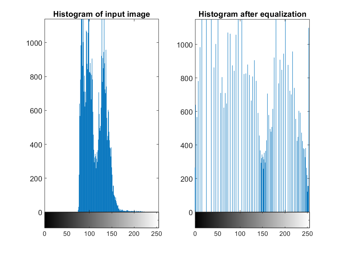
% load image
I = imread('hdlc_pout.tif');

%Write image to FPGA
wrValid1 = writePort(hFPGA, "ImageIn", I);
wrValid2 = writePort(hFPGA, "ImageIn", I);
% Read result from FPGA
[outputFrame1, rdValid1] = readPort(hFPGA, "ImageOut");
% Display result
figure
imagesc([I outputFrame1],[0 255]); colormap(gray)
title('(left) Input image, (right) Output image read from FPGA')
% Display histograms
figure
subplot(1,2,1);imhist(I,256);
title('Histogram of input image')
subplot(1,2,2);imhist(outputFrame1,256);
title('Histogram after equalization')

Limitations
When you generate an IP core from a frame-based algorithm and enable delay mapping to external memory, these limitations apply:
You can map at most one large delay to external memory. If there are multiple large delays over the threshold set by the Delay size threshold for external memory parameter, the largest delay is mapped to external memory while the rest of the delays are mapped to memory on the FPGA.
HDL Coder only maps FIFO blocks as delays generated during HDL code generation to external memory. Delay blocks created from optimizations that add pipelines to the generated model and code cannot be moved outside the DUT and mapped to external memory.
See Also
Topics
- Generate IP Core for Frame-Based Model with AXI4 Stream Interfaces
- Use Neighborhood, Reduction, and Iterator Patterns with a Frame-Based Model or Function for HDL Code Generation
- Generate HDL Code from Frame-Based Models by Using Neighborhood Modeling Methods
- HDL Code Generation from Frame-Based Algorithms
- Model Design for AXI4-Stream Interface Generation