Interface Adapter
A source port and its destination port can be defined by different data interfaces in System Composer™. Such a connection can represent an intermediate point in design, where components from different sources come together. To connect components that have different data interfaces, use an Adapter block and the Interface Adapter dialog box. For interfaces terminology, see Define Port Interfaces Between Components.
An adapter helps connect two components with incompatible port interfaces by mapping between the two interfaces. Use the Adapter block to implement an adapter. Open the Interface Adapter dialog box by double-clicking an Adapter block on the connection between the ports.
With an adapter, on the Interface Adapter dialog box, you can:
Create and edit mappings between input and output interfaces.
Apply an interface conversion
UnitDelayto break an algebraic loop.Apply an interface conversion
RateTransitionto reconcile different sample time rates for reference models.Apply an interface conversion
Mergeto merge two or more message or signal lines.When output interfaces are undefined, you can use input interfaces in bus creation mode to author owned output interfaces.
systemcomposer.openModel("exMobileRobotInterfaces");Map Incompatible Interfaces
When two connected components with Simulink® behaviors have incompatible interfaces, use an Adapter block and the Interface Adapter to define the port connections.
Add an Adapter block on the connection between the two components
SensorandMotor.Rename the port on the
Motorcomponent MotorData.Assign the
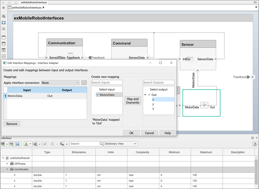
coordinatesinterface to the MotionData port. In the Interface Editor, select thecoordinatesinterface. Then, right-click the port on the System Composer canvas and selectApply selected interface coordinates.Open the Interface Adapter by double-clicking the Adapter block.
In the Select input box, select the
MotorDatadata element. In the Select output box, select thexdata element.Click the Map and Overwrite button.
You have mapped the MotorData port to the MotionData port by mapping to the data element x from the coordinates data interface.
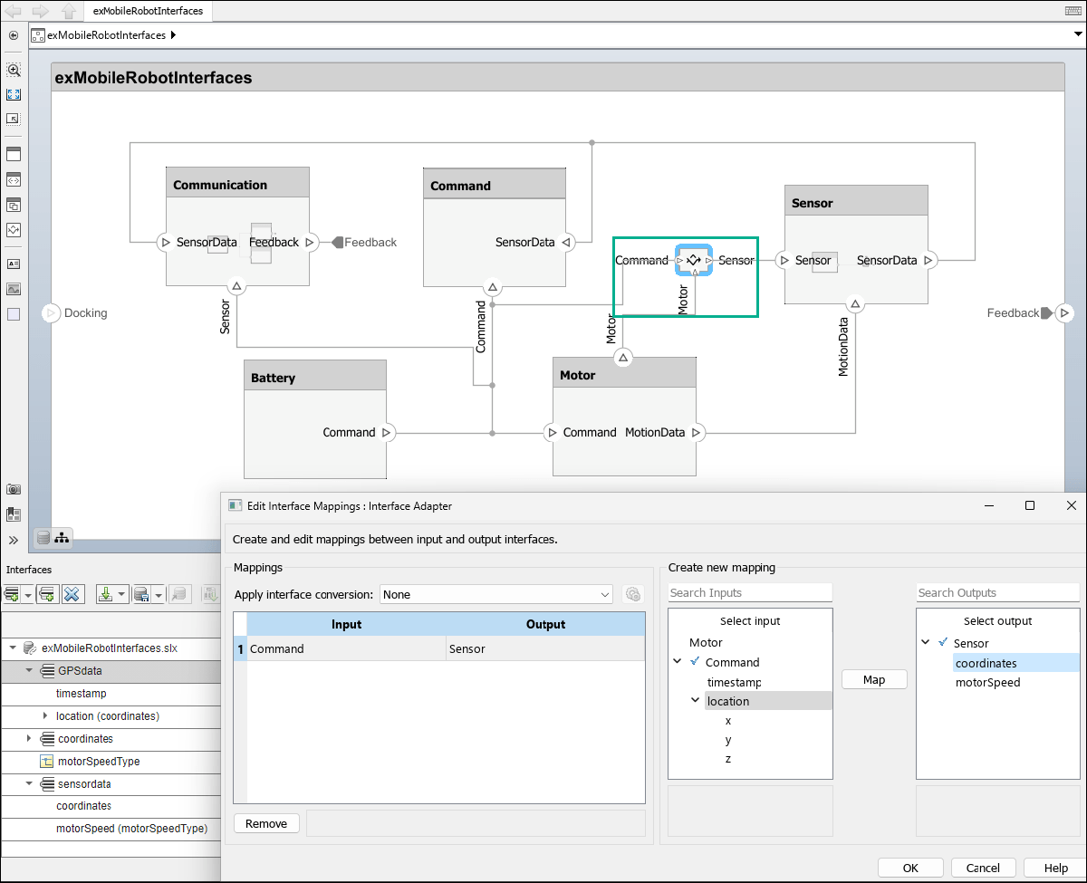
You can use an Adapter block to map similar interfaces for an N:1 connection, which is an Adapter with more than one input port and a single output port. A data element from each input connection maps to the output connection data elements.
Create a Motor output port on the top of the
Motorcomponent. Add an Adapter block on the connection between theSensor,Motor, andCommandcomponents. Change the number of input ports on an Adapter block in the same way you add and remove component ports. For more information, see Compose Architectures Visually.Click the name of each port to edit and rename them. Rename the port on the
Sensorcomponent Sensor, the port on theMotorcomponent Motor, and the port on theCommandcomponent Command.Assign the
sensorDatainterface to the Sensor port. In the Interface Editor, select thesensorDatainterface. Then, right-click the port on the System Composer canvas and selectApply selected interface sensorData.Assign the
GPSDatainterface to the Command port. In the Interface Editor, select theGPSDatainterface. Then, right-click the port on the System Composer canvas and selectApply selected interface GPSData.Open the Interface Adapter by double-clicking the Adapter block.
In the Select input box, select the
locationdata element. In the Select output box, select thecoordinatesdata element.Click the Map button.
On the Adapter block, the data element location associated with the input port Command is now mapped to the data element coordinates associated with the output port Sensor. Now, the Sensor port on the Sensor component can communicate with the Command port on the Command component.
Use Unit Delay to Break Algebraic Loop
When connecting two components with port connections in both directions, an algebraic loop can occur. To break the algebraic loop, use an Adapter block to insert a unit delay between the components.
Add an Adapter block on the connection between the two components.
Open the Interface Adapter by double-clicking the Adapter block.
From the Apply interface conversion list, select
UnitDelay.
You can configure unit delays by clicking the ![]() icon. Options include:
icon. Options include:
Initial conditions — Default
0
For more information, see Remove Algebraic Loops.
Use Rate Transition Between Simulink Behaviors
When connecting two reference components, the Simulink models that the components reference can have different sample time rates. For compatibility, use an Adapter block to insert a rate transition between the components.
Add an Adapter block on the connection between the two components.
Open the Interface Adapter by double-clicking the Adapter block.
From the Apply interface conversion list, select
RateTransition.
You can configure rate transitions by clicking the ![]() icon. Options include:
icon. Options include:
Ensure data integrity during data transfer — Default
trueEnsure deterministic data transfer (maximum delay) — Default
trueInitial conditions — Default
0
For more information, see Data Transfer Representation and Processing (Simulink Coder).
Use Adapter Block as Merge Block
Use an Adapter block as a Merge block to merge multiple message lines for system architecture models or merge multiple message lines or multiple signal and message lines for software architecture models.
Add an Adapter block on the connection between the two components.
Open the Interface Adapter by double-clicking the Adapter block.
From the Apply interface conversion list, select
Merge.
For more information, see Merge Message Connections for Architectures Using Adapter Block.
Use Bus Creation Mode to Author Owned Interfaces
When input ports for an Adapter block are typed by interfaces from incoming connections and no interfaces are defined on the output ports of the adapter, you can use the interface elements from the input ports to author owned interfaces for outgoing connections. An owned interface is an interface that is local to a specific port and not shared in a data dictionary or the model dictionary. Instead of predefining interface structures, you can create the bus structure.
systemcomposer.openModel("SewingMachine");1. Open the Interface Adapter in bus creation mode by double-clicking the Adapter block.
2. Click the ![]() button to add the input data element
button to add the input data element Torque to the output port interface for the port named Signal.

3. Select the Displacement element from the Select output box. Click the ![]() button to remove the output data element
button to remove the output data element Displacement from the output port interface for the port named Signal.
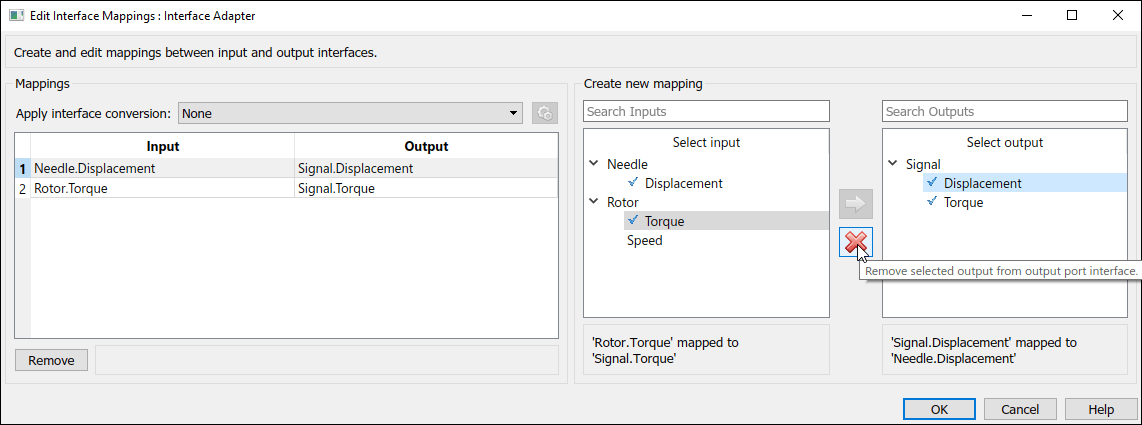
4. Click OK to apply the changes.
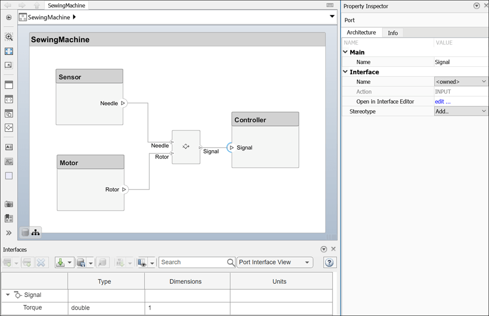
The owned interface on the output port of the Adapter block propagates to the connected input port Signal on the Controller component. The owned interface contains one element, Torque.
To convert an owned interface into a shared interface, right-click the port with the owned interface and select Convert to shared interface.
See Also
Blocks
Objects
Functions
makeOwnedInterfaceShared|IsAdapterComponent|addAdapter|addInput|getInput|connectTo|updatePosition|addMapping|removeMapping