Inverting Topology Buck-Boost Converter Control
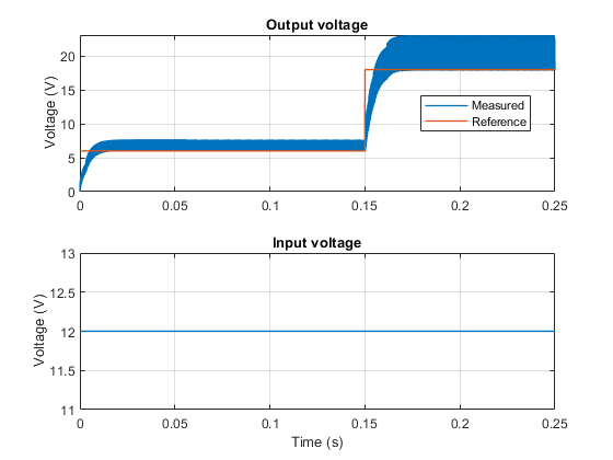
This example shows how to control the output voltage of an inverting topology buck-boost converter. The inverting topology buck-boost converter uses only a single switch and the output voltage is of the opposite polarity than the input. To adjust the duty cycle, the Control subsystem uses a PI-based control algorithm. The input voltage and the system load are considered constant throughout the simulation. The total simulation time (t) is 0.25 seconds. At t = 0.15 seconds, the voltage reference changes and the system switches from buck mode to boost mode.
Model

Simulation Results from Simscape Logging
The plot below shows the requested and measured voltage for the test and the input voltage in the circuit.
See Also
Buck-Boost Converter | DC-DC Voltage Controller