Buck Converter Voltage Control
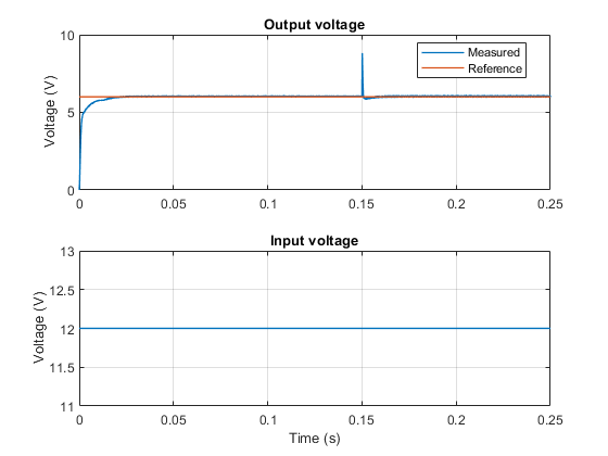
This example shows how to control the output voltage of a buck converter. To adjust the duty cycle, the Control subsystem uses a PI-based control algorithm. The input voltage is considered constant throughout the simulation. A variable resistor provides the load for the system. The total simulation time (t) is 0.25 seconds. At t = 0.15 seconds, the load changes.
Model

Simulation Results from Simscape Logging
The plot below shows the requested and measured voltage for the test and the input voltage in the circuit.
