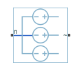
Voltage Source (Three-Phase)
Ideal three-phase voltage source with optional harmonics
Libraries:
Simscape /
Electrical /
Sources
Description
The Voltage Source (Three-Phase) block models an ideal three-phase voltage source or a three-phase voltage source with harmonics. You specify the configuration using the Source representation parameter.
When you select None for the Source
Impedance parameter, the Voltage Source
block models an ideal three-phase voltage source that maintains sinusoidal voltage of
the specified magnitude across its terminals, independently of the current flowing
through the source.
The source has a wye configuration, and port n provides a connection to the center of the wye. Port ~ is an expandable three-phase port representing the three phases, a, b, and c. The current is positive if it flows from the center of the wye to the positive terminal, and the voltage across each phase is equal to the difference between the voltage at the positive terminal and the center of the wye, V(+) – Vn.
Equations
The output voltage for the Voltage Source block is defined by these equations:
where:
V0 is the peak phase voltage.
vline_rms is the root-mean square (RMS) phase-to-phase voltage.
va, vb, vc are the respective phase voltages.
f is frequency.
φ is the phase shift.
t is time.
When you specify the three-phase voltage source with harmonics representation, the output voltage for the Voltage Source block is defined by these equations:
where:
V0 is a row-vector containing the peak voltage of the fundamental and harmonic sinusoids.
vline_rms is the RMS phase-to-phase voltage.
Hratios is a row-vector of harmonic ratios. The first element is 1 to represent the fundamental.
Horders is a row-vector of harmonic orders. The first element is 1 to represent the fundamental.
va, vb, vc are the respective phase voltages.
f is a column-vector of harmonic frequencies. The first element is the fundamental frequency.
φ is a column-vector of harmonic phase shifts. The first element is the fundamental phase shift.
θ is a column-vector of harmonic phase offsets. The first element is
120°.t is the time.
When you select X/R ratio for the Source
Impedance parameter, the equations for source impedance are:
where:
Ssc is the Short-circuit power level that you specify.
ϕ is the Source X/R ratio that you specify.
R is the calculated source resistance.
X is the calculated source reactance.
L is the calculated source inductance.
Variables
To set the priority and initial target values for the block variables before simulation, use the Initial Targets section in the block dialog box or Property Inspector. For more information, see Set Priority and Initial Target for Block Variables.
Nominal values provide a way to specify the expected magnitude of a variable in a model. Using system scaling based on nominal values increases the simulation robustness. You can specify nominal values using different sources, including the Nominal Values section in the block dialog box or Property Inspector. For more information, see System Scaling by Nominal Values.
Ports
Conserving
Parameters
Extended Capabilities
Version History
Introduced in R2013b
