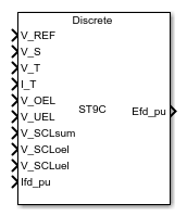
Main Content

SM ST9C

Discrete-time or continuous-time synchronous machine ST9C static excitation system with automatic voltage regulator

Since R2023a

Libraries:
Simscape / Electrical / Control / SM Control

Description

The SM ST9C block implements a synchronous-machine-type ST9C static excitation system model in conformance with IEEE 421.5-2016 [1].

Use this block to model the control and regulation of the field voltage of a synchronous machine.

Switch between continuous and discrete implementations of the block by using the Sample time (-1 for inherited) parameter. To configure the integrator for continuous time, set the Sample time (-1 for inherited) parameter to 0. To configure the integrator for discrete time, set the Sample time (-1 for inherited) parameter to a positive scalar. To inherit the sample time from an upstream block, set the Sample time (-1 for inherited) parameter to -1.

The SM ST9C block comprises four major components:

  • The Current Compensator component modifies the measured terminal voltage as a function of the terminal current.

  • The Voltage Measurement Transducer component simulates the dynamics of a terminal voltage transducer using a low-pass filter.

  • The Excitation Control Elements component compares the voltage transducer output with a terminal voltage reference to produce a voltage error value. The component then passes this value through a voltage regulator to produce the field voltage.

  • The Power Source component models the power source for the controlled rectifier when it is independent from the terminal voltage.

This diagram shows the structure of the ST9C excitation system model:
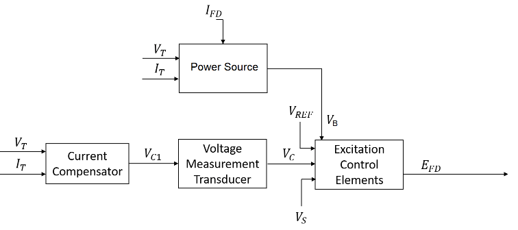
In the diagram:

  • VT and IT are the measured terminal voltage and current of the synchronous machine, respectively.

  • VC1 is the current-compensated terminal voltage.

  • VC is the filtered, current-compensated terminal voltage.

  • VREF is the reference terminal voltage.

  • VS is the power system stabilizer voltage.

  • VB is the exciter field voltage.

  • EFD and IFD are the field voltage and current, respectively.

Current Compensator and Voltage Measurement Transducer

The block models the current compensator by using this equation:

VC1=VT+ITRC2+XC2,

where:

  • RC is the load compensation resistance.

  • XC is the load compensation reactance.

The block implements the voltage measurement transducer as a Low-Pass Filter block with the time constant TR. Refer to the documentation for the Low-Pass Filter block for information about the exact discrete and continuous implementations.

Excitation Control Elements

This diagram shows the structure of the excitation control elements:
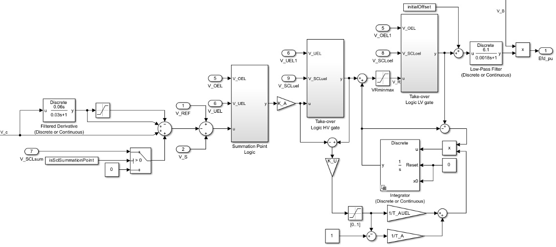
In the diagram:

  • A differential stage in the compensated voltage Vc path provides a faster reaction of the regulator with large voltage variations. A Saturation block eliminates the influence of the differential stage for small changes in Vc, with the Upper limit and Lower limit parameters equal to Z_A, which is the value of the Dead-band for differential part influence on AVR, Z_A (1) parameter.

  • The Summation Point Logic subsystem models the summation point input location for the overexcitation limiter (OEL) and underexcitation limiter (UEL) voltages. For more information about using limiters with this block, see Field Current Limiters.

  • There are two Take-over Logic subsystems. The subsystems model the take-over point input location for the OEL, UEL and SCL. For more information about using limiters with this block, see Field Current Limiters.

  • A Low-Pass Filter block models the power converter stage, where Power converter gain (proportional to supply voltage), K_AS (pu) and Equivalent time constant of power converter firing control, T_AS (s) are the gain and time constant, respectively. The time constant TAS represents the total delay of the gate control unit and power converter. The gain KAS is proportional to the secondary voltage of the power potential transformer that feeds the power converter.

  • The UEL is a PI regulator with its own proportional gain. This PI regulator shares the integral path with the AVR. The integration time constant depends on the error signals of the UEL and AVR. The sign of the difference between the AVR error signal and the V_UELsignal that comes from the UEL model indicates whether the UEL or the AVR is active.

  • The Power source selector parameter controls the origin of the power source for the controlled rectifier. The subsystem multiplies the voltage regulator command signal VR by the exciter field voltage VB. For more information about the logical switch for the power source of the controlled rectifier, see Power Source.

Field Current Limiters

You can use different types of field current limiter to modify the output of the voltage regulator under unsafe operating conditions:

  • Use an overexcitation limiter to prevent overheating of the field winding due to excessive field current demand.

  • Use an underexcitation limiter to boost field excitation when it is too low, which risks desynchronization.

  • Use a stator current limiter to prevent overheating of the stator windings due to excessive current.

Attach the output of any of these limiters at one of these points:

  • Summation point — Use the limiter as part of the automatic voltage regulator (AVR) feedback loop.

  • Take-over points — Override the usual behavior of the AVR.

If you are using the stator current limiter at the summation point, use the input VSCLsum. If you are using the stator current limiter at the take-over point, use the overexcitation input VSCLoel, and the underexcitation input VSCLuel.
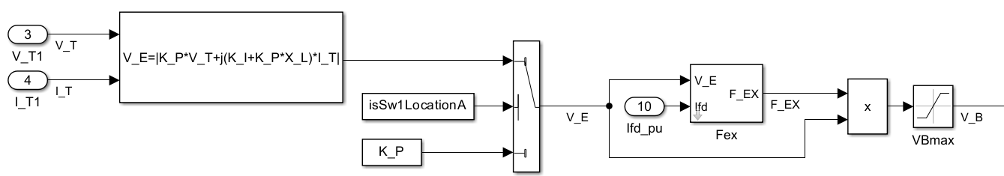
Power Source

You can use different power source representations for the controlled rectifier by setting the Switch to select exciter supply configuration parameter value. To derive the power source for the controlled rectifier from the terminal voltage, set the Switch to select exciter supply configuration parameter to Position A: power source derived from generator terminal voltage. To specify that the power source is independent of the terminal voltage, set the Switch to select exciter supply configuration parameter to Position B: power source independent of generator terminal conditions.

This diagram shows a model of the exciter power source utilizing a phasor combination of the terminal voltage VT and terminal current IT:

Ports

Input

expand all

Voltage regulator reference set point, in per-unit representation, specified as a scalar.

Data Types: single | double

Input from the power system stabilizer, in per-unit representation, specified as a scalar.

Data Types: single | double

Terminal voltage magnitude, in per-unit representation, specified as a scalar.

Data Types: single | double

Terminal current magnitude, in per-unit representation, specified as a scalar.

Data Types: single | double

Input from the overexcitation limiter, in per-unit representation, specified as a scalar.

Dependencies

  • To ignore the input from the overexcitation limiter, set Alternate OEL input locations (V_OEL) to Unused.

  • To use the input from the overexcitation limiter at the summation point, set Alternate OEL input locations (V_OEL) to Summation point.

  • To use the input from the overexcitation limiter at the take-over point, set Alternate OEL input locations (V_OEL) to Take-over.

Data Types: single | double

Input from the underexcitation limiter, in per-unit representation, specified as a scalar.

Dependencies

  • To ignore the input from the underexcitation limiter, set Alternate UEL input locations (V_UEL) to Unused.

  • To use the input from the underexcitation limiter at the summation point, set Alternate UEL input locations (V_UEL) to Summation point.

  • To use the input from the underexcitation limiter at the take-over point, set Alternate UEL input locations (V_UEL) to Take-over.

Data Types: single | double

Input from the stator current limiter when using the summation point, in per-unit representation, specified as a scalar.

Dependencies

  • To ignore the input from the stator current limiter, set Alternate SCL input locations (V_SCL) to Unused.

  • To use the input from the stator current limiter at the summation point, set Alternate SCL input locations (V_SCL) to Summation point.

Data Types: single | double

Input from the stator current limiter that prevents field overexcitation when using the take-over point, in per-unit representation, specified as a scalar.

Dependencies

  • To ignore the input from the stator current limiter, set Alternate SCL input locations (V_SCL) to Unused.

  • To use the input from the stator current limiter at the take-over point, set Alternate SCL input locations (V_SCL) to Take-over.

Data Types: single | double

Input from the stator current limiter that prevents field underexcitation when using the take-over point, in per-unit representation, specified as a scalar.

Dependencies

  • To ignore the input from the stator current limiter, set Alternate SCL input locations (V_SCL) to Unused.

  • To use the input from the stator current limiter at the take-over point, set Alternate SCL input locations (V_SCL) to Take-over.

Data Types: single | double

Measured per-unit field current of the synchronous machine, specified as a scalar.

Data Types: single | double

Output

expand all

Per-unit field voltage to apply to the field circuit of the synchronous machine, returned as a scalar.

Data Types: single | double

Parameters

expand all

General

Initial per-unit voltage to apply to the field circuit of the synchronous machine.

Initial per-unit voltage to apply to the terminal.

Dependencies

To enable this parameter, in the Exciter section, set Switch to select exciter supply configuration to Position A: power source derived from generator terminal voltage.

Initial per-unit current to apply to the terminal.

Dependencies

To enable this parameter, in the Exciter section, set Switch to select exciter supply configuration to Position A: power source derived from generator terminal voltage.

Time between consecutive block executions. During execution, the block produces outputs and, if appropriate, updates its internal state. For more information, see What Is Sample Time? and Specify Sample Time.

For inherited discrete-time operation, set this parameter to -1. For discrete-time operation, set this parameter to a positive integer. For continuous-time operation, set this parameter to 0.

If this block is in a masked subsystem or a variant subsystem that supports switching between continuous operation and discrete operation, promote this parameter to ensure correct switching between the continuous and discrete implementations of the block. For more information, see Promote Block Parameters on a Mask.

Pre-Control

Resistance used in the current compensation system. Set this parameter and Reactance component of load compensation, X_C (pu) to 0 to disable current compensation.

Reactance used in the current compensation system. Set this parameter and Resistive component of load compensation, R_C (pu) to 0 to disable current compensation.

Equivalent time constant for the voltage transducer filtering.

Control

Time constant of the Filtered Derivative block of the differential part of the AVR, in seconds.

Filter time constant of the Filtered Derivative block of the differential part of the AVR, in seconds.

Dead-band of the differential part of the AVR.

Gain of the AVR.

Gain associated with the activation of the takeover UEL.

Time constant of the AVR, in seconds.

Time constant of the UEL, in seconds.

Maximum per-unit output of the regulator.

Minimum per-unit output of the regulator.

Per-unit gain of the power converter gain, proportional to the supply voltage.

Equivalent time constant of the firing control of the power converter, in seconds.

Location of the overexcitation limiter input, specified as one of these options:

  • Summation pointV_OEL is an input of the Summation Point Logic subsystem.

  • Take-overV_OEL is an input of the Take-over Logic subsystem.

Location of the underexcitation limiter input, specified as one of these options:

  • Summation pointV_UEL is an input of the Summation Point Logic subsystem.

  • Take-overV_UEL is an input of the Take-over Logic subsystem.

Location of the stator current limiter input, specified as one of these options:

  • Summation point — Use the V_SCLsum input port.

  • Take-over — Use the V_SCLoel and V_SCLuel input ports.

Exciter

Rectifier loading factor. This value is proportional to the commutating reactance.

Per-unit voltage gain coefficient in the power source circuit.

Per-unit current gain coefficient in the power source circuit.

Dependencies

To enable this parameter, set Switch to select exciter supply configuration to Position A: power source derived from generator terminal voltage.

Per-unit reactance in the compound source.

Dependencies

To enable this parameter, set Switch to select exciter supply configuration to Position A: power source derived from generator terminal voltage.

Phase angle of the power source circuit, in degrees.

Dependencies

To enable this parameter, set Switch to select exciter supply configuration to Position A: power source derived from generator terminal voltage.

Maximum per-unit available exciter voltage value based on supply condition.

Position of the power source selector, specified as Position A: power source derived from generator terminal voltage or Position B: power source independent of generator terminal conditions.

References

[1] IEEE Std 421.5-2016 (Revision of IEEE Std 421.5-2005). "IEEE Recommended Practice for Excitation System Models for Power System Stability Studies." Piscataway, NJ: IEEE, 2016.

Extended Capabilities

C/C++ Code Generation
Generate C and C++ code using Simulink® Coder™.

Version History

Introduced in R2023a