Half-Bridge Driver
Behavioral model of half-bridge driver integrated circuit
Libraries:
Simscape /
Electrical /
Semiconductors & Converters
Description
The Half-Bridge Driver block provides an abstracted representation of an integrated circuit for driving MOSFET and IGBT half-bridges. The block models input hysteresis, propagation delay, and turn-on/turn-off dynamics. Unless modeling a gate driver circuit explicitly, always use this block or the Gate Driver block to set gate-source voltage on a MOSFET block or gate-emitter voltage on an IGBT block. Do not connect a controlled voltage source directly to a semiconductor gate, because this omits the gate driver output impedance that determines switching dynamics.
You can model electrical or physical signal input ports by setting the Modeling option parameter to either:
PS input— The driver output state is controlled by a physical signal input u. Use this modeling option if all of your controller, including PWM waveform generation, is determined by Simulink® blocks. This modeling option is the default.Electrical input ports— The driver output state is controlled by two electrical input connections, PWM and REF. Use this option if your model has upstream analog components, such as the Controlled PWM Voltage source.
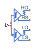
The first pair of output electrical ports, HO and HS, behave in the same way as the G and S ports of the Gate Driver block. Connect these ports to the high-side MOSFET or IGBT of the half-bridge. The second pair of ports, LO and LS, connect to the low-side MOSFET or IGBT of the half-bridge. They behave in a similar way, except that their logic is inverted with respect to that of the high side.
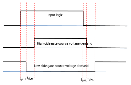
The diagram shows the timing properties for the half-bridge driver, where:
tpLH is low-side propagation delay when the input logic goes from 0 to 1.
tdLH is high-side dead time when the input logic goes from 0 to 1.
tpHL is high-side propagation delay when the input logic goes from 1 to 0.
tdHL is low-side dead time when the input logic goes from 1 to 0.
Faults
To model a fault in the Half-Bridge Driver block, in the Faults section, click Add fault next to the fault that you want to model. For more information about fault modeling, see Fault Behavior Modeling and Fault Triggering.
You can insert a fault into one or both of the outputs at a specified simulation time. The fault options are:
Fail input fixed at logic
                            0
Fail input fixed at logic 1
Fail high side off
Fail high side on
Fail low side off
Fail low side on
Fail high and low sides off
Fail high and low sides on
Examples
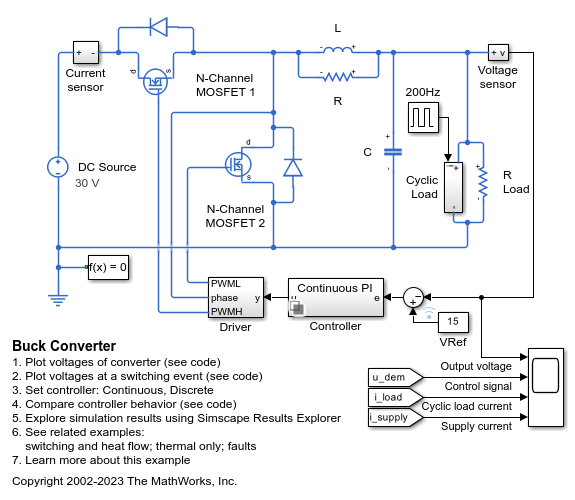
Buck Converter
Model a switching power supply that converts a 30V DC supply into a regulated 15V DC supply. Use this model to size the inductance L and the smoothing capacitor C and to design the feedback controller. Select between continuous and discrete controllers to explore the impact of the discretization.

Buck Converter with Thermal Dynamics
Model a switching power supply that converts a 30V DC supply into a regulated 15V DC supply. The model can be used to both size the inductance L and smoothing capacitor C, as well as to design the feedback controller. By selecting between continuous and discrete controllers, the impact of discretization can be explored. Modeling the switching devices as MOSFETs rather than ideal switches ensures that device on-resistances are correctly represented. The model also captures the switch-on/switch-off timing of the devices, this depending primarily on the gate capacitance values and the PWM driver output resistance.
Ports
Input
Conserving
Parameters
Extended Capabilities
Version History
Introduced in R2017b