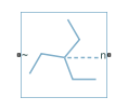
Earthing Transformer
Three-phase earthing transformer in zigzag configuration
Libraries:
Simscape /
Electrical /
Passive /
Transformers
Description
The Earthing Transformer block models a three-phase zigzag-connection earthing or grounding transformer. The block allows you to provide an artificial neutral in an ungrounded three-phase power system. The artificial neutral creates a low-impedance path for the zero-sequence current and high-impedance path for the positive-sequence current. To accommodate a phase-to-neutral load, the return path allows a delta-connected supply.
For more information on using a three-phase zigzag-connection earthing or grounding transformer, see Engineering Applications
![]()
Equations
This block is implemented in both electrical and magnetic domains, representing the physics of phase windings and magnetic core. The equivalent circuit for the block includes windings, reluctances, and eddy currents.
![]()
For a zigzag configuration in magnetic circuit, the a-. b-, and c-phases represent each leg of the magnetic core.
You can obtain the relationship between the electrical and the magnetic properties by applying several mathematical steps based on the magnetic flux conservation rule and on the Hopkinson's law.
For earthing transformers, the couplings between the phases and all the windings are identical. In the equations below:
n is the number of turns of the winding.
R is the magnetizing reluctance between phases.
RL is the leakage reluctance.
Leddy is the magnetic inductance due to eddy current losses between phases.
Then the relationship between the inductance matrix in electrical domain and the reluctance matrix in the magnetic domain can be written as:
The diagonal elements represent the sum of a leakage and magnetizing inductance for each phase, such that:
Therefore:
Ports
Conserving
Parameters
More About
Extended Capabilities
Version History
Introduced in R2019a