Center-Tapped Transformer
Libraries:
Simscape /
Electrical /
Passive /
Transformers
Description
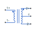
The Center-Tapped Transformer block implements a center-tapped transformer. In switch-mode power supplies applications, you often use a center-tapped transformer inside a full-wave rectifier, which needs the entire DC output from the AC input.
The two electrical networks that connect to the primary and secondary windings of the Center-Tapped Transformer block must each have their own Electrical Reference block. Normally, you also connect the center tap of the secondary winding to an Electrical Reference block.
Equations
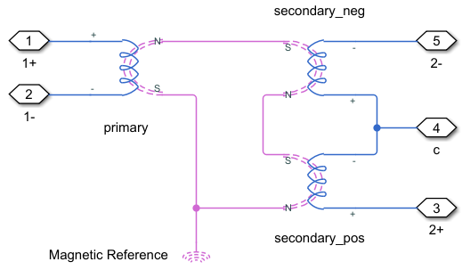
This figure shows the equivalent circuit of the Center-Tapped
Transformer block when you set the Modeling
option parameter to Ideal:

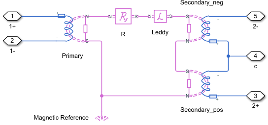
This figure shows the equivalent circuit of the Center-Tapped
Transformer block when you set the Modeling
option parameter to Non-Ideal:

You must determine the relation between the electrical domain parameters from the block mask and the magnetic domain parameters used in the equivalent circuit model:
n is the value of the Winding ratio parameter.
L1 is the value of the Primary leakage inductance parameter.
Rm is the value of the Magnetization resistance parameter.
Lm is the value of the Magnetization inductance parameter.
T is the value of the Center tap position (0~1) parameter.
L2 is the value of the Secondary leakage inductance parameter.
Rw2 is the value of the Secondary winding resistance parameter.
is the primary winding leakage reluctance.
is the shunt magnetizing resistance.
is the conductance of the eddy current loop.
is the secondary winding leakage reluctance.
is the secondary top winding resistance.
is the secondary bottom winding resistance.
Ports
Conserving
Parameters
Extended Capabilities
Version History
Introduced in R2023b
