Specify Joint Motion Profile
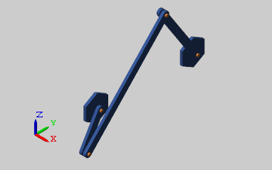
This example shows how to specify the motion of a Revolute Joint block and measure the corresponding actuation torque at the joint. The example uses a four-bar linkage mechanism.
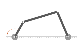
To drive the linkage, you prescribe a time-varying position signal for the crank angle. Then you use the Revolute Joint block to sense the actuation torque at the joint that corresponds to the prescribed motion.
Build Model
At the MATLAB® command prompt, enter
openExample("sm/DocFourBarLinkageModelExample")to open the linkage model. To learn how to build the model, see Model a Closed-Loop Kinematic Chain.Double-click the Base-Crank Revolute Joint block and specify these parameters:
Parameter Setting Actuation > Torque Automatically ComputedActuation > Motion Provided by InputSensing > Actuator Torque Selected The block displays two physical signal ports. Input port q accepts the joint angular position. Output port t provides the joint actuation torque required to achieve the prescribed angular positions.
For each of the four Revolute Joint blocks, in the Internal Mechanics section, set the Damping Coefficient to
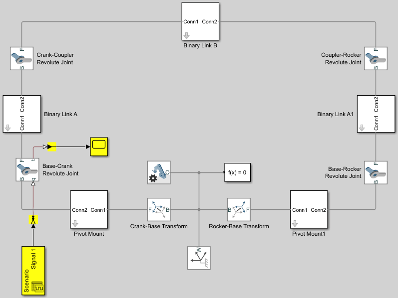
5e-4N*m/(deg/s). During the simulation, damping forces between the joint frames account for dissipative losses at the joints.Add these blocks to the model. These blocks enable you to specify an actuation position signal and plot the actuation torque for the joint.
Block Library Simulink-PS Converter Simscape > Utilities PS-Simulink Converter Simscape > Utilities Scope Simulink > Sinks Signal Editor Simulink > Sources Connect the blocks as shown in the figure.
Double-click the Simulink-PS Converter block and specify these parameters:
Parameter Value Input Heading > Filtering and derivatives Filter input, derivatives calculatedInput Heading > Input filtering order Second-order filteringUse the Signal Editor block to specify the position signal. This example uses the default unit, rad, for the signal. You can change the unit of the input signal by using the Simulink-PS Converter block.
Double-click the Signal Editor block to open the dialog box.
Under Signal properties, click the Launch Signal Editor button
 to open the Signal
Editor window.
to open the Signal
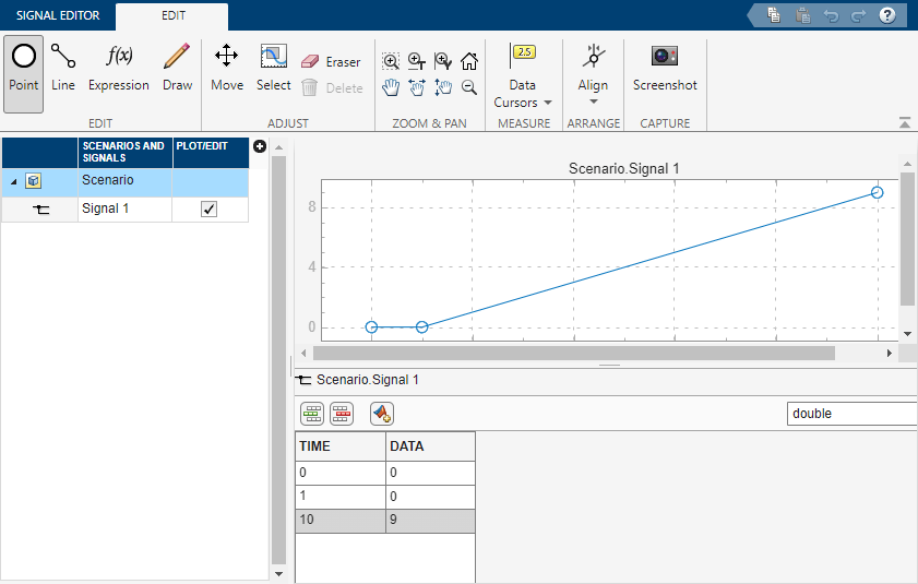
Editor window.In the Signal Editor window, in the left pane, expand Scenario, select the Plot/Edit check box, and edit data as shown in the image. This signal corresponds to a constant angular speed of 1 rad/s from t = 1s onwards.
On the Signal Editor tab, click Save to save the data to a MAT file. Close the Signal Editor window.
In the dialog box, under Signal properties, select Interpolate data, click Apply and OK.
Simulate Model
Run the simulation. Multibody Explorer opens with a dynamic display of the four-bar model.
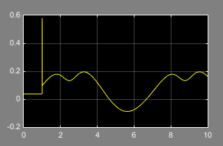
Open the Scope window. The plot shows the joint actuation torque with which you can achieve the motion you prescribed.