PS-Simulink Converter
Convert physical signal into Simulink output signal
Libraries:
Simscape /
Utilities
Description
The PS-Simulink Converter block converts a physical signal into a Simulink® output signal. Use this block to connect outputs of a Simscape™ physical network to Simulink scopes or other Simulink blocks.
Block Icon Display on the Model Canvas
To convey signal conversion while taking up minimal canvas space, the block icon changes dynamically based on whether it is connected to other blocks.
| When Block Is... | Block Icon |
|---|---|
Unconnected |
|
Connected to other blocks |
|
Unit Conversion and Checking
The Output signal unit parameter lets you specify the desired units
for the output signal. These units must be commensurate with the units of the input physical
signal coming into the block. If you specify a desired output unit, the block applies a gain
equal to the conversion factor before outputting the Simulink signal. For example, if the input physical signal coming into the block is
displacement, in meters, and you set Output signal unit to
mm, the block multiplies the value of the input signal by 1e3 before
outputting it. If the output signal unit is the same as the input signal unit, no gain is
applied.
The default value of the Output signal unit parameter,
inherit, automatically sets the unit at the block output port
to match the unit of the input physical signal coming into the block, based on unit
propagation rules. This way, you can easily connect a PS-Simulink
Converter block to any signal, without worrying about setting the
commensurate output unit.
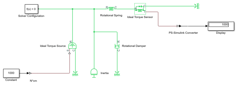
In the diagram below, the input signal for the PS-Simulink
Converter block is torque in N*m, and if you do not specify the output
signal unit, the Display block shows the value of 10. If you change the
Output signal unit parameter value in the PS-Simulink
Converter block to N*cm, the torque value in the
Display block changes to 1000, as shown in the diagram.
When the output signal is related to thermodynamic variables and contains units of temperature, you must decide whether affine conversion needs to be applied. For more information, see When to Apply Affine Conversion. Usually, if the output signal represents a relative temperature, that is, a change in temperature, you need to apply linear conversion, ΔTnew = L * ΔTold (the default method). However, if the output signal represents an absolute temperature, you need to apply affine conversion, Tnew = L * Told + O.
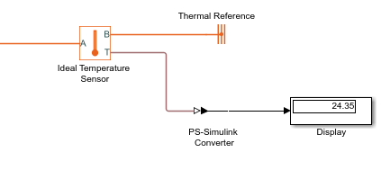
In the following diagram, the Display block shows the room temperature.
If you want to display it in degrees Celsius, open the PS-Simulink
Converter block, type degC in the Output
signal unit field, and select the Apply affine conversion
check box. The display reading is 24.35. However, if you leave the Apply affine
conversion check box clear, the Display block would show
297.5.
Note
Unit specified for the output signal by using the Output signal unit parameter does not propagate outside of the physical network. However, if you also specify a physical unit as an attribute of the Simulink signal connected to the output port of the block, the software checks that the two units match. For more information, see Working with Simulink Units.
Examples
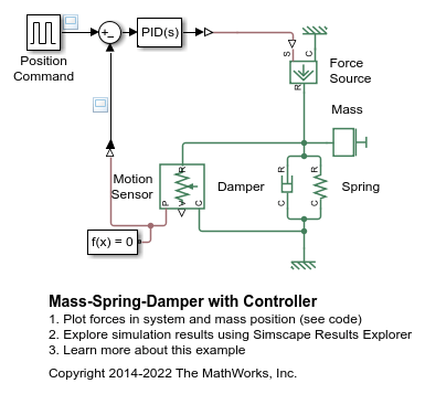
Mass-Spring-Damper with Controller
A controlled mass-spring-damper. A controller adjusts the force on the mass to have its position track a command signal. The initial velocity for the mass is 10 meters per second. The controller adjusts the force applied by the Force Source to track the step changes to the input signal.