Transform Sensor
R2026bSensor that measures the relative spatial relationship between two frames
Transform Sensor block

To add a block to a model, double-click the canvas and start typing the block name. Then, select the block from the list.
Libraries:
Simscape /
Multibody /
Frames and Transforms
Description
The Transform Sensor block measures the relative spatial relationship between frames connected to ports F and B of the block. The measured quantities include the relative pose, velocity, and acceleration, which are time-varying physical signals.
You can measure the absolute translational or rotational quantities of a frame by
connecting the frame ports F and B of the block to
this frame and the world frame of the model, respectively, and setting the
Observation Frame parameter to
World.
Observation Frame and Expressed-In Frame
The Observation Frame and Expressed-In Frame parameters control how the block reports measurements. The Observation Frame parameter specifies the reference frame for computing time derivatives. The Expressed-In Frame parameter specifies the coordinate axes for expressing vector outputs. For details on how these parameters affect each output, see the Output Dependency section.
Rotational and Translational Measurements
The block supports four rotation parameterizations: angle-axis, quaternion, rotation matrix, and rotation sequence. The block also supports three translational coordinate systems: Cartesian, cylindrical, and spherical. For details on these coordinate systems, see the Coordinate Systems section.
Examples
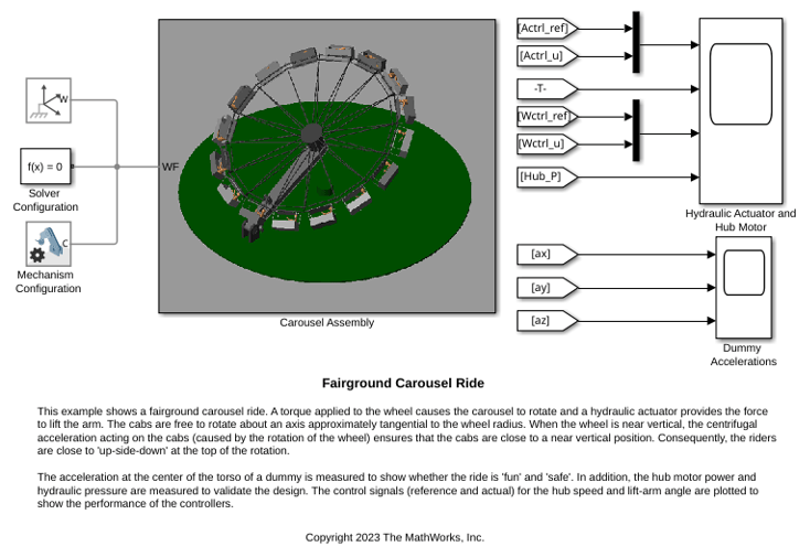
Fairground Carousel Ride
A fairground carousel ride. A torque applied to the wheel causes the carousel to rotate and a hydraulic actuator provides the force to lift the arm. The cabs are free to rotate about an axis approximately tangential to the wheel radius. When the wheel is near vertical, the centrifugal acceleration acting on the cabs (caused by the rotation of the wheel) ensures that the cabs are close to a near vertical position. Consequently, the riders are close to 'up-side-down' at the top of the rotation.
Ports
Frame
Frame port associated with the base frame.
Frame port associated with the follower frame.
Output
Angle of rotation, returned as a scalar. The angle indicates the rotation of the follower frame with respect to the base frame about the axis specified by the vector output by port axs. The angle falls in the range [0, π].
Use ports q and axs to output the rotation signals using the axis-angle parameterization. For more information, see Rotational Measurements.
Dependencies
To enable this port, under Rotation, select Angle.
Axis of rotation, returned as a 3-by-1 unit vector. Use ports q and axs to output the rotation signals using the axis-angle parameterization.
Dependencies
To enable this port, under Rotation, select Axis.
Relative rotation, returned as a quaternion. For more information about the quaternions, see Rotational Measurements.
Dependencies
To enable this port, under Rotation, select Quaternion.
Relative rotation, returned as a 3-by-3 matrix. For more information about the rotation matrix, see Rotational Measurements.
Dependencies
To enable this port, under Rotation, select Transform.
Relative rotation, returned as a 3-by-1 vector. The vector contains the angles for the three successive elementary rotations that represent the rotation of the follower frame with respect to the base frame.
The three rotations are about an intermediate frame and can be one of 12 different rotation sequences. The setting of the Sequence for Rotation Sequence parameter affects the output value. For more information about the rotation sequence measurements, see Rotational Measurements.
Dependencies
To enable this port, under Rotation, select Rotation Sequence.
X-component of the relative angular velocity between the two frames, returned as a scalar. The Expressed-In Frame parameter affects this signal. For details, see the Output Dependency section.
Dependencies
To enable this port, under Angular Velocity, select Omega X.
Y-component of the relative angular velocity between the two frames, returned as a scalar. The Expressed-In Frame parameter affects this signal. For details, see the Output Dependency section.
Dependencies
To enable this port, under Angular Velocity, select Omega Y.
Z-component of the relative angular velocity between the two frames, returned as a scalar. The Expressed-In Frame parameter affects this signal. For details, see the Output Dependency section.
Dependencies
To enable this port, under Angular Velocity, select Omega Z.
Angular velocity of the follower frame with respect to the base frame, returned as a 3-by-1 vector. The Expressed-In Frame parameter affects this signal. For details, see the Output Dependency section.
Dependencies
To enable this port, under Angular Velocity, select Omega XYZ.
Relative angular velocity, returned as a 4-by-1 vector that equals the time derivative of the signal from port Q.
Dependencies
To enable this port, under Angular Velocity, select Quaternion.
Relative angular velocity, returned as a 3-by-3 matrix. The matrix equals the time derivative of the signal from port R.
Dependencies
To enable this port, under Angular Velocity, select Transform.
Relative angular velocity, returned as a 3-by-1 vector. The vector equals the time derivative of the output from the port seq. The Sequence for Rotation Sequence parameter setting affects the output value.
Dependencies
To enable this port, under Angular Velocity, select Rotation Sequence.
X-component of the relative angular acceleration between the two frames, returned as a scalar. The Observation Frame and Expressed-In Frame parameters affect this signal. For details, see the Output Dependency section.
Dependencies
To enable this port, under Angular Acceleration, select Alpha X.
Y-component of the relative angular acceleration between the two frames, returned as a scalar. The Observation Frame and Expressed-In Frame parameters affect this signal. For details, see the Output Dependency section.
Dependencies
To enable this port, under Angular Acceleration, select Alpha Y.
Z-component of the relative angular acceleration between the two frames, returned as a scalar. The Observation Frame and Expressed-In Frame parameters affect this signal. For details, see the Output Dependency section.
Dependencies
To enable this port, under Angular Acceleration, select Alpha Z.
Angular acceleration of the follower frame with respect to the base frame, returned as a 3-by-1 vector. The Observation Frame and Expressed-In Frame parameters affect this signal. For details, see the Output Dependency section.
Dependencies
To enable this port, under Angular Acceleration, select Alpha XYZ.
Relative angular acceleration, returned as a 4-by-1 vector.
Dependencies
To enable this port, under Angular Acceleration, select Quaternion.
Relative angular acceleration, returned as a 3-by-3 matrix.
Dependencies
To enable this port, under Angular Acceleration, select Transform.
X-component of the relative translation between the two frames, returned as a scalar. The Expressed-In Frame parameter affects this signal. For details, see the Output Dependency section.
Dependencies
To enable this port, under Translation, select X.
Y-component of the relative translation between the two frames, returned as a scalar. The Expressed-In Frame parameter affects this signal. For details, see the Output Dependency section.
Dependencies
To enable this port, under Translation, select Y.
Z-component of the relative translation between the two frames, returned as a scalar. The Expressed-In Frame parameter affects this signal. For details, see the Output Dependency section.
Because both the Cartesian and cylindrical coordinate systems have the z-axis, the Transform Sensor block has only one output port for both coordinate systems.
Dependencies
To enable this port, under Translation, select Z.
Translation of the follower frame with respect to the base frame, returned as a 3-by-1 vector expressed in the Cartesian coordinate system. The Expressed-In Frame parameter affects this signal. For details, see the Output Dependency section.
Dependencies
To enable this port, under Translation, select XYZ.
Cylindrical radius coordinate of the relative translation vector, returned as a nonnegative scalar. The Expressed-In Frame parameter affects this signal. For details, see the Output Dependency section.
Dependencies
To enable this port, under Translation, select Radius.
Azimuth of the relative translation vector, returned as scalar. The angle falls in the range of [-π, π). The azimuth is undefined if the origins of the base and follower frames coincide with each other. The Expressed-In Frame parameter affects this signal. For details, see the Output Dependency section.
Because the azimuth exists in both the cylindrical and spherical coordinate systems, the Transform Sensor block has only one output port for both coordinate systems.
Dependencies
To enable this port, under Translation, select Azimuth.
Spherical radius coordinate of the relative translation vector, returned as a scalar. The value equals the distance between the origins of the base and follower frames.
Dependencies
To enable this port, under Translation, select Distance.
Inclination of the relative translation vector, expressed in the spherical coordinate system, returned as a scalar. The angle falls in the range of [-π/2, π/2]. The Expressed-In Frame parameter affects this signal. For details, see the Output Dependency section.
Dependencies
To enable this port, under Translation, select Inclination.
X-component of the relative linear velocity between the two frames, returned as a scalar. The Observation Frame and Expressed-In Frame parameters affect this signal. For details, see the Output Dependency section.
Dependencies
To enable this port, under Velocity, select X.
Y-component of the relative linear velocity between the two frames, returned as a scalar. The Observation Frame and Expressed-In Frame parameters affect this signal. For details, see the Output Dependency section.
Dependencies
To enable this port, under Velocity, select Y.
Z-component of the relative linear velocity between the two frames, returned as a scalar. The Observation Frame and Expressed-In Frame parameters affect this signal. For details, see the Output Dependency section.
Because both the Cartesian and cylindrical coordinate systems have the z-axis, the Transform Sensor block has only one output port for both coordinate systems.
Dependencies
To enable this port, under Velocity, select Z.
Linear velocity of the follower frame with respect to the base frame, returned as a 3-by-1 vector expressed in Cartesian coordinate system. The Observation Frame and Expressed-In Frame parameters affect this signal. For details, see the Output Dependency section.
Dependencies
To enable this port, under Velocity, select XYZ.
Cylindrical radius coordinate of the relative linear velocity, returned as a scalar. The Observation Frame and Expressed-In Frame parameters affect this signal. For details, see the Output Dependency section.
Dependencies
To enable this port, under Velocity, select Radius.
Azimuth coordinate of the relative linear velocity, returned as a scalar. The Observation Frame and Expressed-In Frame parameters affect this signal. For details, see the Output Dependency section.
Because the azimuth coordinate exists in both the cylindrical and spherical coordinate systems, the Transform Sensor block has only one output port for both coordinate systems.
Dependencies
To enable this port, under Velocity, select Azimuth.
Spherical radius coordinate of the relative linear velocity, returned as a scalar.
Dependencies
To enable this port, under Velocity, select Distance.
Inclination coordinate of the relative linear velocity, expressed in the spherical coordinate system, returned as a scalar. The Observation Frame and Expressed-In Frame parameters affect this signal. For details, see the Output Dependency section.
Dependencies
To enable this port, under Velocity, select Inclination.
X-component of the relative linear acceleration between the two frames, returned as a scalar. The Observation Frame and Expressed-In Frame parameters affect this signal. For details, see the Output Dependency section.
Dependencies
To enable this port, under Acceleration, select X.
Y-component of the relative linear acceleration between the two frames, returned as a scalar. The Observation Frame and Expressed-In Frame parameters affect this signal. For details, see the Output Dependency section.
Dependencies
To enable this port, under Acceleration, select Y.
Z-component of the relative linear acceleration between the two frames, returned as a scalar. The Observation Frame and Expressed-In Frame parameters affect this signal. For details, see the Output Dependency section.
Because both the Cartesian and cylindrical coordinate systems have the z-axis, the Transform Sensor block has only one output port for both coordinate systems.
Dependencies
To enable this port, under Acceleration, select Z.
Linear acceleration of the follower frame with respect to the base frame, returned as a 3-by-1 vector expressed in Cartesian coordinate system. The Observation Frame and Expressed-In Frame parameters affect this signal. For details, see the Output Dependency section.
Dependencies
To enable this port, under Acceleration, select XYZ.
Cylindrical radius coordinate of the relative linear acceleration, returned as a scalar. The Observation Frame and Expressed-In Frame parameters affect this signal. For details, see the Output Dependency section.
Dependencies
To enable this port, under Acceleration, select Radius.
Azimuth coordinate of the relative linear acceleration, returned as a scalar. The Observation Frame and Expressed-In Frame parameters affect this signal. For details, see the Output Dependency section.
Because the azimuth coordinate exists in both cylindrical and spherical coordinate systems, the Transform Sensor block has only one output port for both coordinate systems.
Dependencies
To enable this port, under Acceleration, select Azimuth.
Spherical radius coordinate of the relative linear acceleration, returned as a scalar.
Dependencies
To enable this port under Acceleration, select Distance.
Inclination coordinate of the relative linear acceleration, expressed in the spherical coordinate system, returned as a scalar. The Observation Frame and Expressed-In Frame parameters affect this signal. For details, see the Output Dependency section.
Dependencies
To enable this port, under Acceleration, select Inclination.
Parameters
Reference frame with respect to which the block computes time derivatives. Use this parameter to specify from whose perspective the block observes motion when computing velocity and acceleration.
| Setting | Description |
|---|---|
World | The block computes time derivatives with respect to the world frame. |
Base | The block computes time derivatives with respect to the base frame. |
Follower | The block computes time derivatives with respect to the follower frame. |
This parameter affects linear velocity, linear acceleration, and angular acceleration outputs. For details, see the Output Dependency section.
Coordinate frame whose axes the block uses to express vector outputs. Use this parameter to specify the x-, y-, and z-axes that the block projects vectors onto.
| Setting | Description |
|---|---|
World | The block expresses vector outputs in world frame axes. |
Base | The block expresses vector outputs in base frame axes. |
Follower | The block expresses vector outputs in follower frame axes. |
This parameter affects translation, linear velocity, linear acceleration, angular velocity, angular acceleration, and rotation axis outputs. For details, see the Output Dependency section.
Sequence of the rotation axis for three successive elementary rotations. See Rotation Sequence Measurements for more information.
More About
The Observation Frame and Expressed-In Frame parameters affect block outputs:
Observation Frame determines the reference frame for computing time derivatives. Changing this parameter changes the physical quantity that the block computes because any two observers with non-zero relative angular velocity measure different velocities and accelerations for the same moving body. For example, a rotating observer and a non-rotating observer measure different velocities and accelerations. Similarly, two rotating observers also measure different velocities and accelerations if the relative angular velocity between them is non-zero.
Expressed-In Frame determines which coordinate axes the block uses to express vector outputs. Changing this parameter changes only the numerical components that represent the vector. The physical vector remains the same.
When both parameters select the same frame, velocity outputs equal the time derivatives of the corresponding position outputs, and acceleration outputs equal the time derivatives of the corresponding velocity outputs.
The following table shows which output ports each parameter affects.
| Output Port | Observation Frame | Expressed-In Frame |
|---|---|---|
| Angle q | No | No |
| Axis axs | No | No |
| Quaternion Q | No | No |
| Rotation Matrix R | No | No |
| Rotation Sequence seq | No | No |
| Angular Velocity wx, wy, wz, w | No | Yes |
| Angular Velocity Qd, Rd, seqd | No | No |
| Angular Acceleration bx, by, bz, b | Yes | Yes |
| Angular Acceleration Qdd, Rdd | No | No |
| Translation x, y, z, p, rad, azm, inc | No | Yes |
| Distance dst, vdst, adst | No | No |
| Linear Velocity vx, vy, vz, v, vrad, vazm, vinc | Yes | Yes |
| Linear Acceleration ax, ay, az, a, arad, aazm, ainc | Yes | Yes |
The block expresses rotational measurements using one of four parameterizations. To enable a parameterization, in the block dialog box, under Rotation, select the corresponding parameter. For example, select the Angle and Axis parameters to use the angle-axis parameterization, or select the Quaternion, Transform, or Rotation Sequence parameter to use the quaternion, rotation matrix, or rotation sequence parameterization.
The block also supports various parameterizations for rotational velocities and accelerations: x-, y-, and z- coordinates; the time derivatives of a quaternion or rotation sequence; or matrix. To enable these parameterizations, select the corresponding parameters under Angular Velocity or Angular Acceleration. For more information, see Rotational Measurements.
The block expresses translational measurements in Cartesian, cylindrical, or spherical coordinates. You can select one or more coordinate systems at the same time. To use a specific coordinate system, select the corresponding parameters. For example, under Velocity, select the X, Y, and Z parameters to express the measured relative linear velocity in Cartesian coordinates. For more information, see Translational Measurements.
The following tables summarize the coordinates of the three translational systems. In
the diagrams, the Expressed-In Frame parameter is set to
Base.
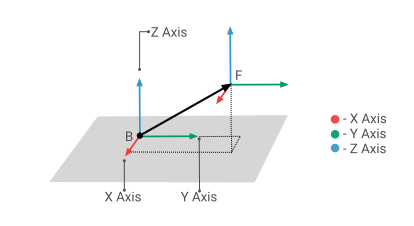
Cartesian Coordinates
| Coordinate | Description |
|---|---|
| X | The projection of the vector BF on the
x-axis of the expressed-in frame. |
| Y | The projection of the vector BF on the
y-axis of the expressed-in frame. |
| Z | The projection of the vector BF on the
z-axis of the expressed-in frame. |
Cylindrical Coordinates
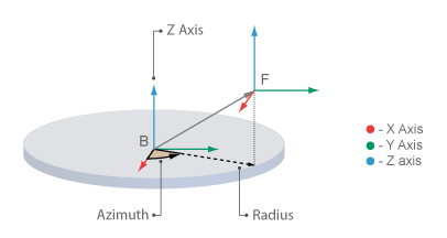
| Coordinate | Description |
|---|---|
| Radius | The length of the projection of the vector BF, in the
x-y plane of the expressed-in frame. |
| Azimuth | The angle of the Radius with respect to the positive
x-axis of the expressed-in frame. The angle falls in the range
of [-π, π). |
| Z | The projection of the vector BF on the
z-axis of the expressed-in frame. |
Spherical Coordinates
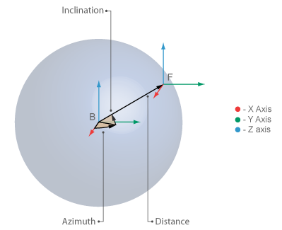
| Coordinate | Description |
|---|---|
| Distance | The distance between origins of the base and follower frames. |
| Azimuth | The angle of the projection of the vector BF in the
x-y plane with respect to the positive
x-axis. The angle is expressed in the expressed-in frame and
falls in the range of [-π, π). |
| Inclination | The angle of the vector BF with respect to the
x-y plane of the expressed-in frame. The angle falls in the
range of [-π/2, π/2]. |
Extended Capabilities
C/C++ Code Generation
Generate C and C++ code using Simulink® Coder™.
Version History
Introduced in R2012aThe Observation Frame and Expressed-In Frame parameters replace the Measurement Frame parameter. These new parameters provide independent control over the reference frame used for computing time derivatives and the coordinate frame used for expressing outputs.
Models saved with the Measurement Frame parameter continue to load and simulate correctly. The block automatically maps the legacy setting to the equivalent combination of the new parameters.
MATLAB Command
You clicked a link that corresponds to this MATLAB command:
Run the command by entering it in the MATLAB Command Window. Web browsers do not support MATLAB commands.
Select a Web Site
Choose a web site to get translated content where available and see local events and offers. Based on your location, we recommend that you select: .
You can also select a web site from the following list
How to Get Best Site Performance
Select the China site (in Chinese or English) for best site performance. Other MathWorks country sites are not optimized for visits from your location.
Americas
- América Latina (Español)
- Canada (English)
- United States (English)
Europe
- Belgium (English)
- Denmark (English)
- Deutschland (Deutsch)
- España (Español)
- Finland (English)
- France (Français)
- Ireland (English)
- Italia (Italiano)
- Luxembourg (English)
- Netherlands (English)
- Norway (English)
- Österreich (Deutsch)
- Portugal (English)
- Sweden (English)
- Switzerland
- United Kingdom (English)
