Camera Manager
Create, edit, and delete dynamic cameras
Description
The Camera Manager tool creates, edits, and deletes cameras with dynamic viewpoints in the Multibody Explorer tool.
You can configure a dynamic camera by using either tracking mode or keyframe mode:
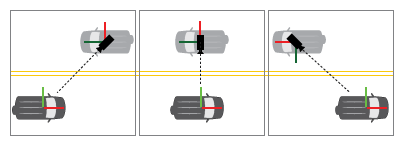
Tracking Mode: Use this mode to set the camera to follow a specific object or point in the simulation. Use this mode to maintain a consistent perspective relative to a moving part, such as simulating the view from a driver or following a specific component throughout the simulation.
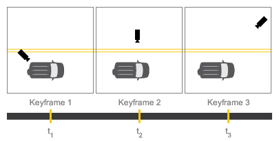
Keyframe Mode: Use this mode to create a custom camera path that is not tied to a specific object. Use keyframes define specific camera positions and orientations at various times, with smooth transitions between them. Use this mode to create cinematic effects or highlight different aspects of the simulation at various times.
To select a camera for the visualization pane, right-click the pane and select a predefined camera. If the visualization pane is split into tiles, you can assign a different camera to each tile. All dynamic cameras use a perspective projection to capture the visualization contents.
Open the Camera Manager
In the Multibody Explorer
toolstrip, in the App tab, click Camera Manager
![]() .
.
Examples
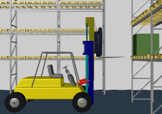
This example shows how to create dynamic cameras for a multibody model. You create two types of dynamic cameras to view an operating forklift. The first camera uses the tracking mode to show the perspective of a driver, and the second relies on several specified keyframes.
Open the example and run the Forklift.slx model. Clear all the existing visualization tiles by clicking Single in the Setup section in the Multibody Explorer toolstrip.
Create a Camera That Uses Tracking Mode
To create a camera that uses tracking mode, constrain the position, aim, and up vector of the camera to selected frames within the model. During the multibody animation, the camera follows these associated frames. First, create a frame to position the camera.
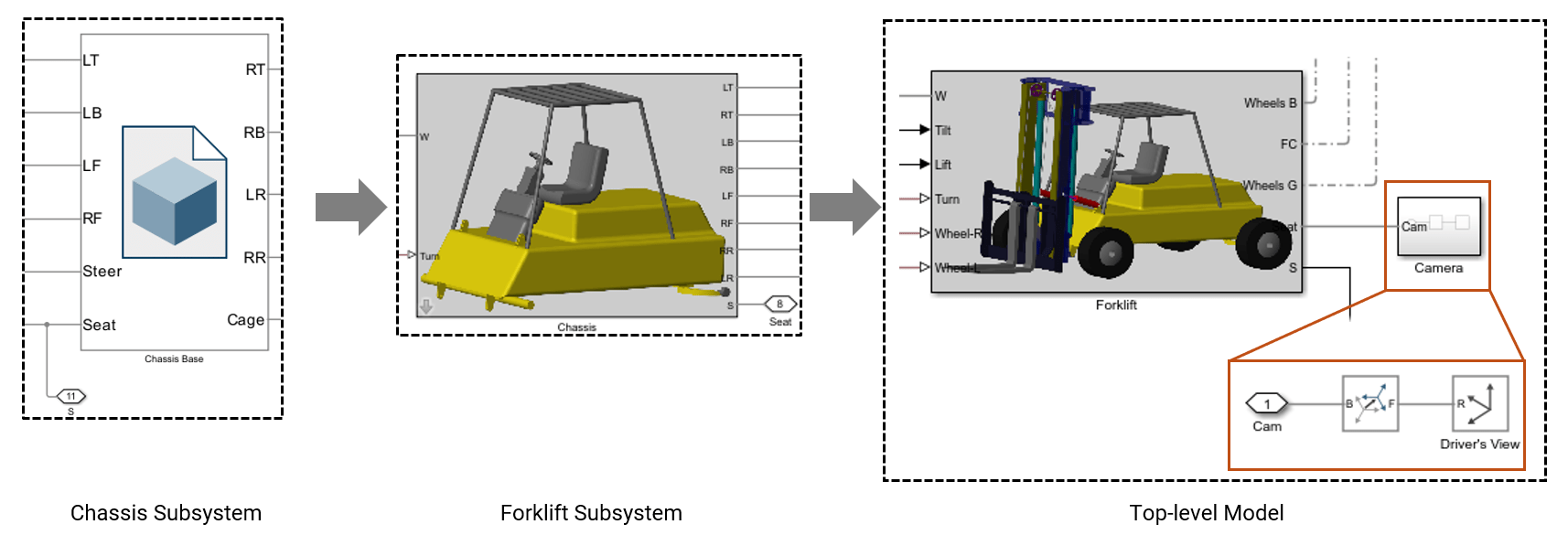
Open the
Chassissubsystem in theForkliftsubsystem. Add an output port S to the Chassis Base as shown in the image.In the
Forkliftsubsystem, add an output port Seat and connect it to the S port of theForkliftsubsystem.At the top level of the model, add a Reference Frame block to represent the location of the driver. Name this block Driver's View and connect it to the Seat port using a Rigid Transform block.
Create a subsystem that includes both the Reference Frame block and the Rigid Transform block. Name this subsystem
Camera.In the
Camerasubsystem, name the connection portCam. Use the Rigid Transform block to define the offset between the driver's view and the seat of the forklift. In the Rigid Transform block, under the Translation section, set Method toStandardAxis, Axis to+Y, and Offset to 75 cm.
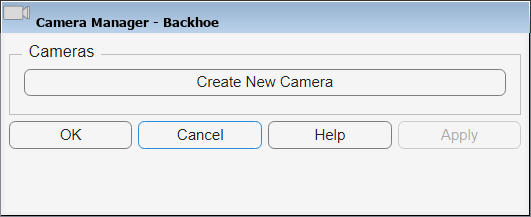
To create the camera that captures the view of a driver, open the Camera Manager and follow these steps:
To start a new camera, click Create New Camera.
To define the camera name, in the Camera Name field, enter
Driver's view.To use the tracking mode, set Mode to
Tracking.To constrain the origin of the camera to the origin of the frame that represents the driver, in the Model Tree pane, navigate to Camera > Driver's View > R. In the Camera Manager, under the Position section, click the Use Selected Frame button.
To align the up vector of the camera with the y-axis of the R frame, in Up vector section, select
+Yand click the Use Selected Frame button.To aim the camera at the bottom of the box, in the Model Tree pane, navigate to Warehouse > Lift Box > Box > Frame1. In the Camera Manager, under the Aim section, select
At Originand click the Use Selected Frame button.To create the camera, click Save, then click OK to exit the Camera Manager.
Create a Camera That Uses Keyframe Mode
To create a camera that uses the keyframe mode, specify keyframes at various playback times to allow Simscape™ Multibody™ to interpolate the frames and create a smooth camera trajectory.
Create a new camera for the keyframe view:
To create a new camera, click the Create New Camera button.
To define the camera name, in the Camera Name field, enter
Keyframes.To use the tracking mode, set Mode to
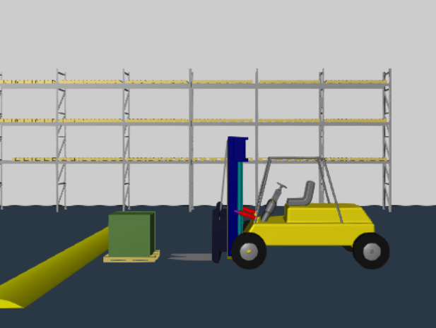
Keyframes.In the visualization pane, set the playback time to 0 s. Adjust the view the front and zoom in as shown in the image. Then, click the Set button.
Tips: You can use the Left and Right arrow keys to navigate to the previous or next simulation time step in the visualization.
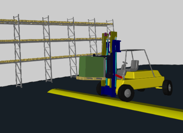
Set the playback time to 17 s, and adjust the view as shown in the image by using the pan, roll, and zoom functionalities. Then, click the Set button.
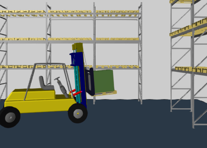
Set the playback time to 24 s, and adjust the view as shown in the image by using the right view and zoom functionalities. Then, click the Set button.
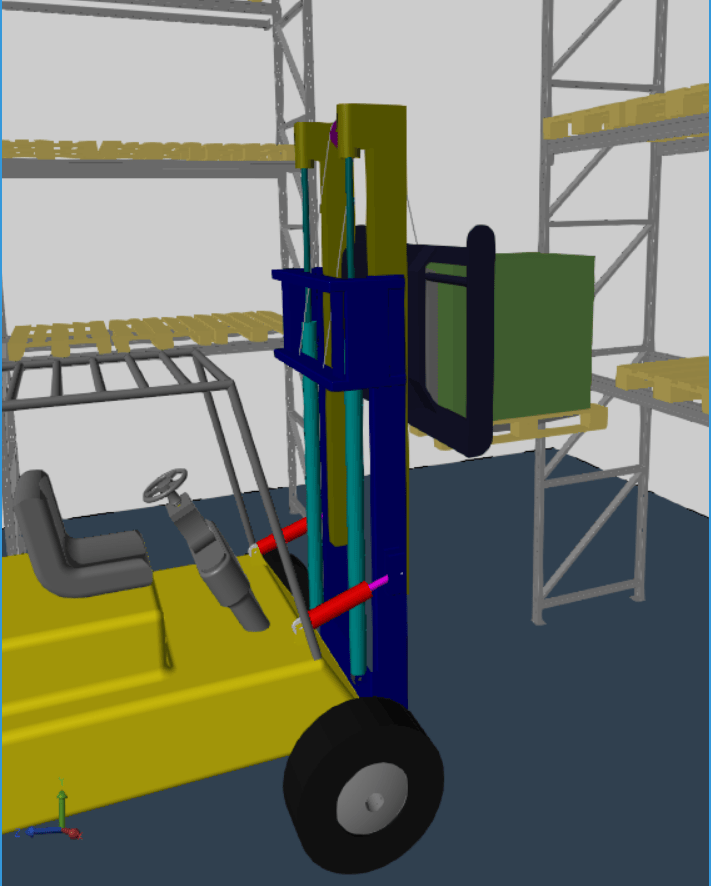
Set the playback time to 39 s, and adjust the view as shown in the image by using the pan, roll, and zoom functionalities. Then, click the Set button.
Change the playback time to 53 s, and adjust the view as shown in the image by using the right view and zoom functionalities. Then, click the Set button.
To create the camera, click Save, then click OK to exit the Camera Manager.
Next, create two vertical split tiles by clicking Split Vertical in the Setup section in the Multibody Explorer toolstrip. Use the left tile for the camera view in tracking mode, and the right tile for the keyframe mode camera view. To assign the driver's view camera to the left tile, right-click the tile and set the Camera parameter to Driver's view. For the right tile, right-click the tile and set Camera to Keyframes. To view the animation through both cameras, click the play button.
Related Examples
Parameters
Version History
Introduced in R2016a