Generate and Export Tests from Requirements Table Blocks
If you create models that contain Requirements Table blocks and you generate tests with Simulink® Design Verifier™, you can export the tests to the Simulink Test Manager (Simulink Test). When configuring the tests, you can specify the test harness that you want to use. After running the tests, you can determine if the tests fail or pass, and inspect the results further.
Construct the Model and Generate Tests
Simulink Design Verifier creates test objectives from the requirements defined in Requirements Table blocks. To generate tests, construct a model, called the specification model, with Requirements Table blocks and Simulink blocks that do not define test objectives. See Construct Specification Models by Using Requirements Table Blocks. After you create the requirements, confirm that the requirement set in each Requirements Table block is complete and consistent by analyzing them. See Identify Inconsistent and Incomplete Formal Requirement Sets. If you do not create complete and consistent requirements, Simulink Design Verifier may not be able to create tests that satisfy the test objectives.
After constructing the requirements, generate tests in the specification model.
In the Apps tab, click Design Verifier.
In the Mode section, set the mode to Test Generation.
In the Prepare section, click Test Generation Settings. The Requirements Table block supports test generation with decision, condition, MCDC, enhanced MCDC, and relational boundary coverage objectives. Specify the objectives in the Model coverage objectives parameter. For more information on these options, See Model Coverage Objectives for Test Generation (Simulink Design Verifier). Click OK.
In the Analyze section, click Generate Tests. Simulink Design Verifier indicates how many objectives from the requirements are satisfied.
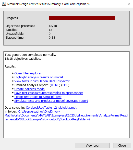
If at least one of the objectives is not satisfied, update your requirements. If you did not analyze the requirements before, analyze them now.
Export the Tests to the Test Manager
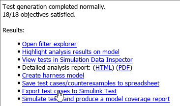
If you have Simulink Test™, you can export the tests to the Test Manager. In the Simulink Design Verifier Results Summary window, click Export test cases to Simulink Test.
The Export Design Verifier Test Cases window displays the properties that you can adjust before exporting.
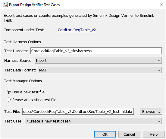
For more information on the properties you can select, see Export Test Cases to Simulink Test (Simulink Design Verifier).
Run the Tests
After exporting the tests, Simulink Test registers the requirements in the Requirements Table blocks to the test cases they generate. To view these assignments, open the Test Manager. Then select the test case in the Test Browser pane. In the Test Case pane, expand the Iterations section.

If you have a manually created test harness that you want to run the tests on, in the Test Browser pane, select the test case and expand System Under Test. In the Model field, specify the model, and clear the model from the Harness field.
Inspect Test Failures
If one of your tests fail, you may need investigate causes of the failure. If you use verification blocks in your harness to verify the outputs of your design and specification model, or if you capture design model outputs in requirement postconditions, you can use property proving on the test harness and run Model Slicer to identify the conditions that cause an assertion failure.
Open the test harness model.
In the Design Verifier tab, in the Mode section, select Property Proving.
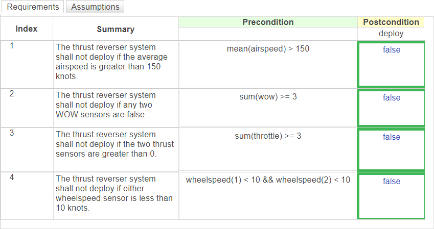
In the Prepare section, click Property Proving Settings. If your specification model uses at least one postcondition, the Requirements Table block highlights the postconditions green if the associated proof objectives are satisfied, red if they are not, and orange for other conditions.
If you use verification blocks, Simulink Design Verifier highlights the blocks that assert a failure in red.
If you use verification blocks, select the highlighted verification block. In the Results window, click debug. The model displays the values that correspond to each signal that caused the failure. These values only display outside of the Requirements Table block.
For more information, see Debug Property Proving Violations by Using Model Slicer (Simulink Design Verifier) and Prove Properties with Requirements Table Blocks.